An OEM integrates a high-resolution display into their new imaging system, only for customers to complain about inconsistent image quality. The "top-spec" monitor fails in a real-world clinical environment.
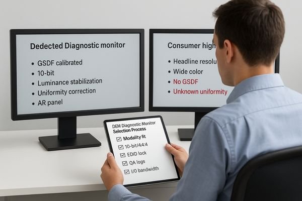
OEMs most often stumble in three places: choosing by marketing pixels instead of modality needs; skipping DICOM GSDF, luminance stabilization, and uniformity QA; and neglecting the end-to-end signal path (10-bit/4:4:4, EDID) and controlled reading environment.
For Original Equipment Manufacturers (OEMs) in the medical imaging space, the choice of a diagnostic monitor is one of the most critical decisions in system design. The display is the final, crucial link where digital data becomes a clinically actionable image. A mistake here can compromise the performance of the entire system, leading to dissatisfied customers, regulatory hurdles, and damaged brand reputation. However, the selection process is fraught with pitfalls. It is easy to be swayed by impressive-sounding specifications like "8K resolution" while overlooking the nuanced requirements of specific clinical modalities. True diagnostic performance is not defined by a single number but by a holistic system of precision, consistency, and stability. This article exposes the three most common and costly mistakes OEMs make when choosing diagnostic monitors and provides a clear, actionable framework for making the right choice every time.
Mistake #1: Choosing by marketing pixels, not modality needs
A monitor’s total pixels are not a proxy for clinical suitability—fit to modality is the first principle.
Picking monitors by headline specs ignores modality fit. A mismatch in pixel pitch, viewing distance, or grayscale capabilities causes scaling artifacts, dilutes low-contrast detail, and ultimately slows down clinical reads.
The most frequent error is evaluating a monitor based on its total pixel count (e.g., 4K, 8K) without considering the specific demands of the intended medical imaging modality. Different clinical tasks have vastly different requirements for how those pixels are delivered.
Pixel Pitch and Viewing Distance
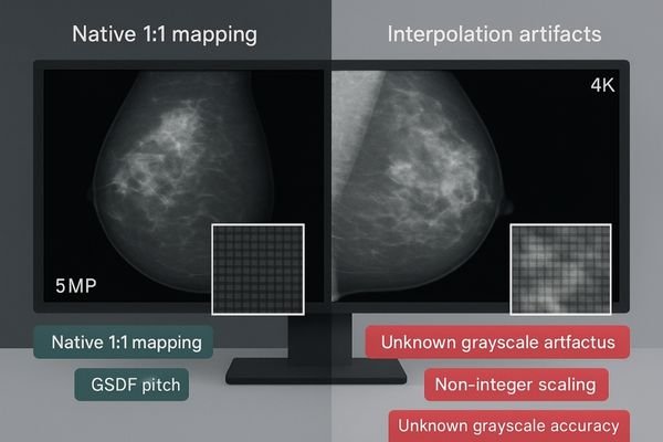
For PACS and CT/MR imaging, a 3–4MP display often provides the right balance of resolution and usable screen real estate for efficient workflow. Mammography, however, demands a much finer pixel pitch to resolve micro-calcifications, making a 5MP or higher resolution monitor1 essential. Simply using a large 8K consumer display is not a solution. Its pixel density may be inadequate, and forcing a medical image to scale to a non-native resolution can introduce interpolation artifacts that either obscure or mimic pathology.
Modality → Pixel pitch × Viewing distance (concrete values):
- PACS / CT / MR: 3–4MP · pixel pitch 0.155–0.210 mm · viewing distance 0.60–0.80 m · native mapping preferred
- Mammography: ≥5MP · pixel pitch ≤0.165 mm (typ. 0.160–0.165 mm for 5MP 21.3") · viewing distance 0.45–0.60 m · strict native mapping
- General comparison reading: 4–8MP · pixel pitch 0.160–0.200 mm · viewing distance 0.60–0.90 m · avoid non-integer scaling
Common non-native scaling artifacts to watch for: softening/blur, ringing/halo on edges, and staircase/banding on gradients.
Grayscale Fidelity over Color Volume
Diagnostic imaging—especially grayscale-critical modalities—relies on distinguishing hundreds of subtle shades of gray. A display should provide true 10-bit grayscale and a calibrated GSDF (Grayscale Standard Display Function) to preserve low-contrast detail. Choosing a consumer display optimized for wide color volume over grayscale accuracy risks losing diagnostic information and slowing reading times.
Mistake #2: Skipping DICOM, luminance stabilization, and uniformity QA
A diagnostic display is not a fixed component—its performance drifts over time. QA is a process, not a checkbox.
Without GSDF checks, luminance stabilization, and uniformity correction, display performance inevitably drifts due to aging and environmental changes, breaking day-to-day consistency and leaving quality assurance unauditable.
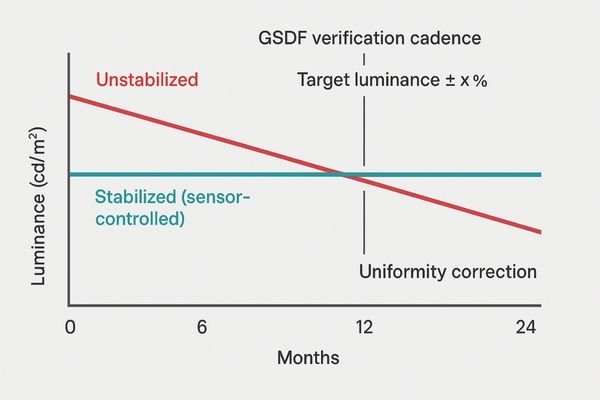
The second critical mistake is treating a diagnostic display as static. Performance is a dynamic state, affected by backlight aging, temperature, and room conditions. Integrating a display without automated QA features invites inconsistency and non-compliance.
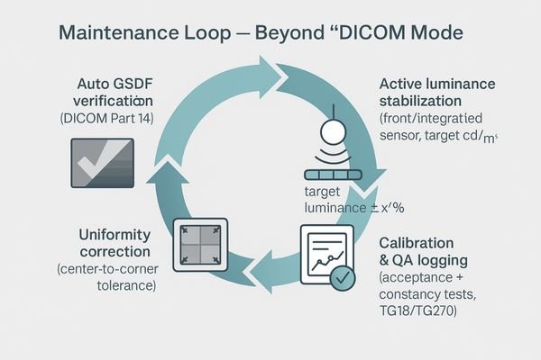
Beyond a "DICOM Mode"
Adopt a four-step maintenance loop (actionable SOP):
- Auto GSDF verification2 (perceptual match checks to DICOM Part 14) at a defined cadence: daily visual check, monthly automated GSDF verification, and annual 18-point quantitative testing by a medical physicist.
- Active luminance stabilization via an integrated/front sensor to a target L′max 350 cd/m² (general diagnostics) / 420 cd/m² (mammography) with tolerance ±10% of the calibrated target.
- Uniformity correction to maintain spatial luminance consistency at Maximum Luminance Deviation < 15% (≈ uniformity ≥ 85%) at acceptance and during constancy QA.
- Calibration & QA logging to a central store, tied to acceptance and constancy tests (e.g., AAPM TG18/TG270).
The Importance of Auditable Logs
Skipping formal acceptance and constancy tests or failing to maintain verifiable logs makes it difficult for end-users to prove compliance during audits and reflects poorly on the OEM system as a whole.
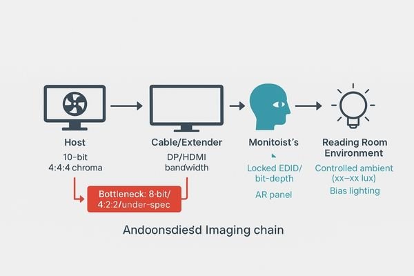
Mistake #3: Neglecting the signal path and reading environment
A great panel can be undone by a weak signal path or poor room conditions—one weak link breaks the chain.
An 8-bit pipeline, incorrect chroma subsampling, weak cabling, or bad EDID management can trigger banding and latency. One weak link—display, signal, or environment—breaks the entire imaging chain.
The diagnostic monitor does not exist in a vacuum. Its output depends on the integrity of the signal and the environment in which it is viewed.
The Digital Pipeline Bottleneck
A 10-bit panel fed by an 8-bit signal will show grayscale banding. Incorrect chroma subsampling (e.g., 4:2:2 instead of 4:4:4) and low-quality or over-long cabling can degrade signal integrity and introduce latency. Poor EDID and bit-depth management causes unstable handshakes and unexpected mode switches.
Must-haves (signal path): end-to-end 10-bit3 · 4:4:4 chroma · adequate bandwidth I/O (DP <x.x> / HDMI <x.x>) · locked EDID/bit-depth policies
Red lines (do not): 8-bit output · 4:2:2 for diagnostic reads · under-spec extenders/cables · unmanaged EDID
The Environment as a Component
Uncontrolled ambient light and reflections create veiling glare that washes out near-black detail. Specify a controlled reading room with illuminance <xx–xx lux>, bias lighting behind the display, avoidance of direct glare sources, and use of anti-reflective (AR) panels where appropriate.
Quick Fix: Lock resolution, GSDF, 10-bit pipeline, and environment
A simple five-point system brings consistency without overhauling the entire design.
Build a system by mapping modality to resolution, ensuring a 10-bit/4:4:4 pipeline with locked EDID, using displays with full QA features, standardizing room lighting, and enforcing clear testing SOPs.
- Map each modality to resolution & pixel pitch (favor native 1:1 pixel mapping; avoid non-integer scaling).
- Engineer end-to-end 10-bit / 4:4:4 with locked EDID/bit-depth; validate I/O bandwidth (
DP <x.x> / HDMI <x.x>). - Select diagnostic monitors with GSDF verification, luminance stabilization, uniformity correction, auto-cal, and logs.
- Standardize room lighting (illuminance
<xx–xx lux>, bias lighting) and fixed reading presets. - Enforce acceptance & constancy tests (TG18/TG270) with archived, auditable logs.
Buying Checklist: OEM diagnostic monitor shortlist
Prioritize features that deliver durable diagnostic value—not just headline specs.
Evaluate monitors based on modality fit, true 10-bit capability with GSDF calibration, integrated stabilization and uniformity correction, high-bandwidth I/O, auditable QA logs, and lifecycle readiness.
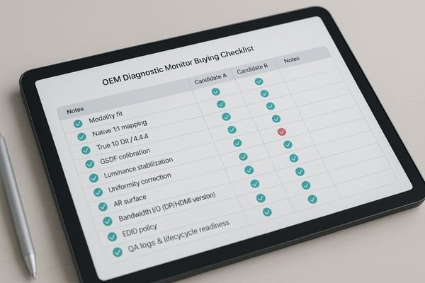
Note: Feature cells below are placeholders—confirm against current datasheets before publishing.
OEM Diagnostic Monitor Shortlist
| Model | Resolution / Size | 10-bit | GSDF & Auto-Cal | Luminance Stabilization | Uniformity Correction | AR | I/O | Primary Use |
|---|---|---|---|---|---|---|---|---|
| MD33G | 3MP / 21.3" | Yes | Yes | Yes | Yes | Yes | DP <x.x> / HDMI <x.x> |
General PACS, CT, MR |
| MD46C | 4MP | Yes | Yes | Yes | Yes | Yes | DP <x.x> / HDMI <x.x> |
Detailed PACS, multimodality comparison |
| MD85CA | 8MP / 31.5" | Yes | Yes | Yes | Yes | Yes | DP <x.x> / HDMI <x.x> |
Single-screen multimodality, wide FOV |
| MD120C | 12MP | Yes | Yes | Yes | Yes | Yes | DP <x.x> / HDMI <x.x> |
Ultra-high density, flexible layouts |
| MD52G | 5MP / 21.3" | Yes | Yes | Yes | Yes | Yes | DP <x.x> / HDMI <x.x> |
Dual-head mammo, DBT |
For specs or demo images: info@reshinmonitors.com
FAQ
Is a consumer 8K display better than a medical 3–5MP display?
Not necessarily. For diagnostic imaging, pixel pitch, grayscale accuracy, and built-in QA are far more important than headline resolution. A weak signal pipeline or lack of proper GSDF calibration can nullify a high pixel count, making a purpose-built medical display the better clinical choice.
Is a 10-bit pipeline4 essential?
Yes. For visualizing subtle, low-contrast lesions and avoiding contouring/banding artifacts in gradients, a true, end-to-end 10-bit pipeline is crucial. OEMs should mandate 10-bit support from the graphics card through to the panel and lock 4:4:4 chroma for maximum signal integrity.
Can different monitor brands be used together in a system?
Yes, with rigorous standardization. If mixing brands, implement a unified policy for GSDF calibration, white point, and user presets. Enforce a consistent QA schedule and lock EDID/bit-depth strategies across all workstations to achieve perceptual consistency.
How strictly should the ambient environment be controlled?
Maintain low and repeatable illuminance <xx–xx lux>, use bias lighting behind the display to reduce eye strain, and avoid direct glare on the screen surface. Combine these controls with a monitor that has a high-quality anti-reflective (AR) panel.
Conclusion
Define monitor resolution by clinical tasks, not marketing numbers; turn subjective perception into objective data with auditable QA; and remember that only a locked display-signal-environment chain can sustain consistent and efficient diagnostic reads. 🧠
- Modality first, pixels second
- 10-bit + GSDF + stabilization + uniformity → logged
- Locked signal path & controlled environment = reproducible reads
👉 For expert guidance and Reshin’s diagnostic display solutions, contact info@reshinmonitors.com.
-
Exploring this topic will highlight the significance of high-resolution monitors in detecting critical details in mammography. ↩
-
Understanding Auto GSDF verification is crucial for ensuring compliance and quality in medical imaging systems. ↩
-
Understanding 10-bit color depth can enhance your knowledge of display technology and improve your viewing experience. ↩
-
Understanding the importance of a 10-bit pipeline can enhance your display’s performance, especially for medical imaging. ↩