Ensuring a PACS monitor is compliant with DICOM Part 14 can feel abstract. Without a practical quality assurance process, diagnostic confidence erodes as displays drift out of specification.
To verify DICOM Part 14 in practice, warm up the display, set room lux to operating levels, run TG18-QC for a quick visual gate, then measure GSDF with a photometer to confirm curve fit and Lmin/Lmax. Check uniformity (e.g., TG18-UNL), document results against TG270 thresholds, and lock profiles to prevent drift; repeat on a fixed constancy schedule.
Maintaining diagnostic image quality is a foundational responsibility for any clinical imaging department. While modern medical displays come with promises of DICOM compliance1, this is not a one-time factory setting; it is a state that must be actively verified and maintained. The American Association of Physicists in Medicine (AAPM) provides a clear roadmap with its Task Group 18 (TG18) test patterns and Task Group 270 (TG270) guidance on quality control2. This guide translates that formal guidance into a practical, repeatable program that separates initial acceptance testing from routine constancy checks. By implementing these steps, you can build an audit-ready QA log, detect display failures before they impact patient care, and ensure that every radiologist is reading from a consistent, calibrated canvas.
What “DICOM Part 14 Verified” Really Means: GSDF, JNDs, Conformance
Many believe that "DICOM mode" on a monitor guarantees compliance. This misunderstanding leads to a false sense of security, as true conformance can only be confirmed through measurement, not by simply toggling a setting.
Verification means the monitor’s Grayscale Standard Display Function (GSDF) has been measured and confirmed to align with the perceptually linear JND standard under specific viewing conditions, ensuring consistent grayscale presentation.
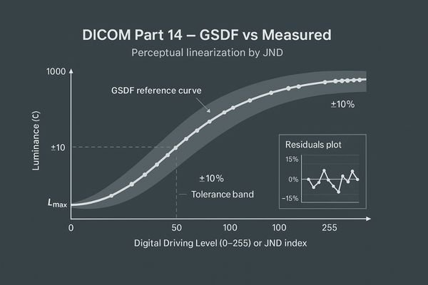
When a monitor is advertised as "DICOM Part 14 Verified3," it means more than just having a "DICOM" preset in its on-screen menu. True conformance is a measurable state. DICOM Part 14 specifies the Grayscale Standard Display Function (GSDF)4, a standardized luminance response curve. This curve is designed to be perceptually linear, meaning that each incremental step in the digital driving level results in a change in brightness that is perceived as equally significant by the human eye. These steps are known as Just-Noticeable Differences (JNDs). Verification, therefore, is the process of using a calibrated photometer to measure the monitor’s luminance at various grayscale levels and confirming that its response curve matches the GSDF within acceptable tolerances. This ensures that two different compliant displays will present the same medical image with the same contrast characteristics, which is the cornerstone of consistent image interpretation. Advanced diagnostic monitors like the MD85CA are built to maintain this compliance with high precision.
TG270 In Practice: Acceptance vs. Constancy Tests, Roles & Intervals
Without a structured program, QA becomes sporadic and ineffective. This leads to inconsistent documentation and the risk that display issues will go unnoticed until they cause a diagnostic error.
A practical TG270 program separates a comprehensive, one-time acceptance test from lean, periodic constancy checks. This approach ensures thorough initial validation while making routine QA efficient and sustainable for the long term.
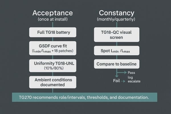
The AAPM’s TG270 guidance provides a framework for structuring a practical quality control program. The key insight is to separate testing into two distinct categories: acceptance testing5 and constancy testing. Acceptance testing is a comprehensive, one-time-only process performed when a new monitor is first installed. It involves running the full battery of TG18 tests and using a photometer to perform a detailed GSDF curve fit analysis. This establishes a detailed performance baseline for that specific display. In contrast, constancy testing6 is a leaner, periodic check designed to be performed quickly and regularly (e.g., quarterly or monthly) by a technologist or physicist. It typically involves a visual check using the TG18-QC pattern and a quick spot-check of key luminance values. If any of these quick checks fail or show significant drift from the baseline, it triggers an escalation to more comprehensive testing. A monitor such as the MD32C with built-in auto-calibration features can significantly streamline this process by automating many of the constancy checks.
Five-Minute Screen-Side Check: Running TG18-QC the Right Way
Visual checks can seem subjective and easy to rush. If the TG18-QC pattern is not used systematically, critical issues like poor sharpness or low-contrast visibility can be easily missed.
The TG18-QC pattern is a powerful screening tool. Systematically evaluate its line pairs, contrast patches, and corner squares to reliably surface issues with sharpness, grayscale tracking, and uniformity in just a few minutes.
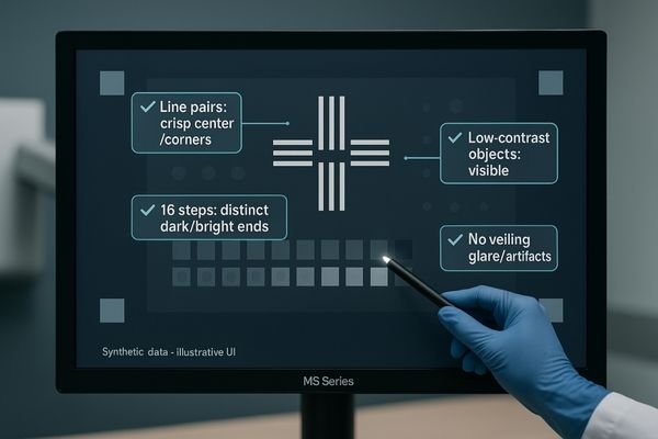
The TG18-QC test pattern7 is arguably the most valuable tool for rapid, routine quality control. When used correctly, it is far more than a simple "box-checking" exercise. This visual test should be performed systematically. First, inspect the high-contrast line-pair patterns at the center and corners to assess display sharpness and resolution. All patterns should be distinct. Next, evaluate the 16 luminance patches to ensure that each grayscale step is distinguishable from its neighbors, paying close attention to the patches at the low-luminance (near black) and high-luminance (near white) ends. Then, check the low-contrast objects embedded within the larger gray squares; their visibility is a direct indicator of the monitor’s ability to display subtle diagnostic information. Finally, assess the overall appearance for any non-uniformity, artifacts, or significant veiling glare. A technologist can perform this entire check in under five minutes. For many grayscale-focused disciplines, a monitor like the MD33G is designed to provide exceptional stability, making routine TG18-QC checks consistently pass.
Measuring GSDF: Photometer Setup, Lmin/Lmax Targets, Fitting & Report
Simply owning a photometer doesn’t guarantee an accurate GSDF measurement. Improper setup, incorrect targets, or flawed reporting can invalidate the entire QA process and create a false sense of compliance.
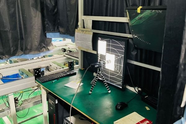
For an accurate GSDF measurement, warm up the display for 30 minutes, position the photometer correctly, measure Lmin and Lmax, and then fit the full curve. The residuals of this fit determine conformance.
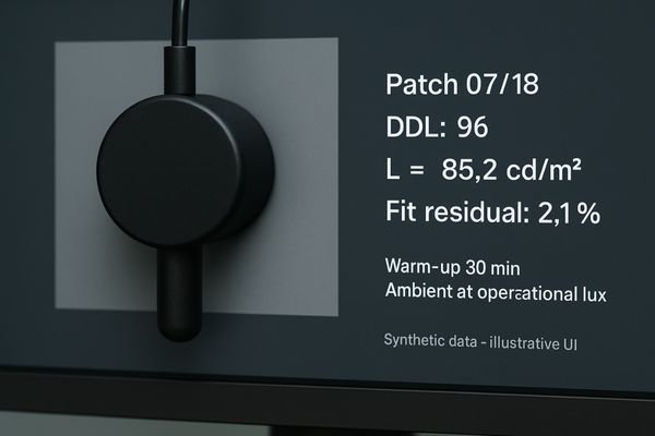
Measuring the GSDF is the core quantitative task in DICOM Part 14 verification8. The process must be meticulous. First, the monitor must warm up for at least 30 minutes to achieve stable luminance output. The room should be set to the typical ambient light level used for clinical reading. The photometer must be positioned securely and perpendicularly to the screen, centered on each test patch. The first measurements are of Lmin (the luminance of black, or digital driving level 0) and Lmax (the luminance of white). These values are critical as they define the boundaries of the monitor’s performance. Next, measure the luminance of all 18 grayscale patches of the TG18-LN pattern. This data is then entered into a software tool or spreadsheet that fits it to the DICOM GSDF curve9. The output should not just be a "pass/fail" result but a report showing the percentage deviation (or JND fit residuals) at each point. This detailed report, not just a simple checkmark, is the auditable proof of conformance.
Uniformity, Reflections, Viewing Angle: TG18-UNL, TG18-AD & Visual Criteria
A display that is only compliant in the center is not truly compliant. Non-uniformity, reflections, and poor viewing angles can hide or mimic pathology, directly impacting diagnostic accuracy across the screen.
Beyond GSDF, test for luminance uniformity using the TG18-UNL pattern at low and high levels. Also, use the TG18-AD pattern to visually assess reflections and viewing angle performance against standard criteria.
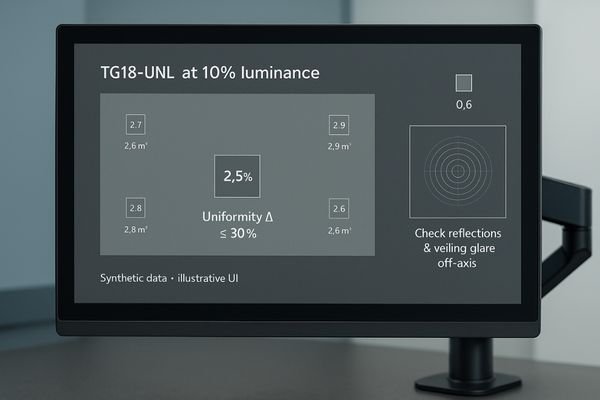
While GSDF conformance is critical, it only describes the monitor’s performance at the center of the screen. AAPM TG18 provides additional patterns to evaluate other important characteristics. Luminance uniformity10 is one of the most vital. This is tested using the TG18-UNL patterns, which display the screen at 10% and 80% luminance levels. By measuring the luminance at the center and each of the four corners, you can calculate the uniformity deviation, which should ideally be within 30%. Poor uniformity can alter how anatomy is perceived near the edges of an image. The TG18-AD11 (Ambient-Reflection-Display) pattern is used for a visual assessment. It contains concentric circles that help reveal veiling glare and distorting reflections from ambient light. When viewing this pattern from off-axis angles, it also provides a clear indication of how the monitor’s contrast and color perform when not viewed head-on. A quality monitor like the MD46C is engineered to excel in these areas, providing a consistent image across the entire panel.
Calibrate Where You Read: Ambient Light Control & Operational Lux
Calibrating a monitor in a dark room and then using it in a bright one is a recipe for failure. The interaction between screen luminance and ambient light is a critical factor that is often overlooked.
True compliance requires calibrating and testing the monitor under the exact ambient light conditions of its clinical use. This "operational lux" is a critical parameter that must be controlled and documented.
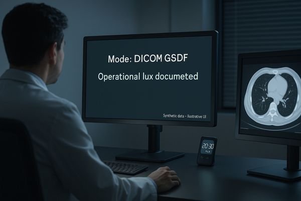
The principle of "calibrate where you read" is non-negotiable for meaningful QA. The DICOM GSDF curve12 is dependent on the ambient light level in the room, as this light adds to the monitor’s emitted luminance, especially affecting the dark end of the curve (Lmin). Calibrating a monitor in a pitch-black office and then moving it to a reading room with overhead lighting will immediately invalidate that calibration. The correct procedure is to first measure and establish a standard "operational lux" level for your reading rooms. This level should be documented in your QA policy. All subsequent acceptance and constancy tests must be performed under this specific lighting condition. Monitors equipped with an Ambient Light Control (ALC) sensor13, like the MD45C, can help automate this process by actively measuring ambient light and adjusting the display’s calibration to maintain GSDF conformance across a range of conditions. This feature provides an essential layer of stability in real-world clinical environments.
| Task | Rationale |
|---|---|
| Measure room light | Establish a standard "operational lux" for the reading environment. |
| Calibrate in situ | Perform all QA tests under the standardized operational lux. |
| Use ALC | Leverage built-in sensors to automatically compensate for light changes. |
| Document conditions | Record the ambient light level as part of every QA report. |
Audit-Ready QA: Thresholds, Templates, and Fleet-Level Logs
Inconsistent or missing documentation is a major red flag during an audit. If you cannot produce a clear and complete log of your QA activities, you cannot prove compliance.
Create standardized templates for all QA tests, define clear pass/fail thresholds, and centralize all results in a fleet-level log. This turns your QA program into an organized, audit-ready compliance system.
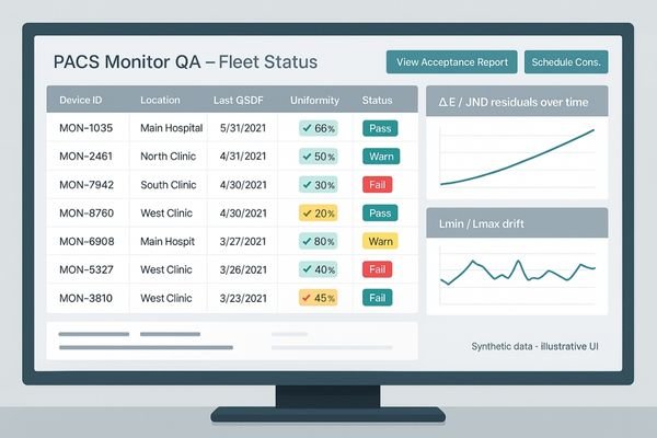
Passing an audit is not just about performing the tests; it is about documenting them flawlessly. The foundation of an audit-ready QA program is the creation of standardized templates14 for every test. These forms should include fields for the monitor’s serial number, the photometer’s ID, the date, the performing technologist’s name, the measured operational lux, and the results of each test against pre-defined pass/fail thresholds. For quantitative tests like GSDF and uniformity, the raw data and calculated deviations should be attached. Rather than storing these reports in a physical binder, they should be centralized in a digital, fleet-level management system15. This could be a dedicated asset management tool or even a specific section within your PACS. This central log allows for easy retrieval during an audit and enables you to track performance trends across your entire fleet of displays, such as the high-luminance MD52G monitors used for mammography, which have their own specific performance requirements.
Failure Modes & Fixes: Drift, Mode Mix-ups, Warm-up, Profile Locks
Even with a perfect QA program, monitors can and will fail. Not knowing how to identify and troubleshoot common failure modes leads to extended downtime and puts a strain on department resources.
Common failures include luminance drift, incorrect display mode selection, and insufficient warm-up time. Mitigate these by using profile locks, enforcing warm-up protocols, and having clear triggers for recalibration whenever drift is detected.
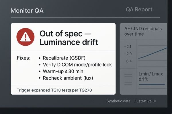
A mature QA program includes procedures for identifying and addressing common failure modes. One of the most frequent is luminance drift16, where the monitor’s brightness slowly changes over time. This is precisely what routine constancy checks are designed to catch, triggering a recalibration. Another common error is a "mode mix-up17," where a user inadvertently changes the display from its calibrated DICOM mode to a generic "Web" or "Video" preset. High-end monitors like the MD120C often include profile lock features to prevent this. Insufficient warm-up time is another source of error; QA must only be performed after the monitor has been on for at least 30 minutes. Finally, OS or graphics driver updates can sometimes overwrite custom calibration profiles. The best mitigation is a robust system of triggers: any failure on a TG18-QC check or any measured value falling outside of your established thresholds should automatically launch an expanded diagnostic and recalibration workflow.
Conclusion
A practical QA program combines TG270 principles with TG18 patterns to create documented, repeatable proof of DICOM Part 14 conformance, ensuring consistent and reliable diagnostic image quality. 📊
👉 For expert guidance and Reshin diagnostic display solutions, contact martin@reshinmonitors.com.
-
Understanding DICOM compliance is crucial for ensuring high-quality diagnostic images and effective patient care. ↩
-
Exploring quality control methods can enhance imaging accuracy and reliability, ultimately improving patient outcomes. ↩
-
Understanding DICOM Part 14 is crucial for ensuring accurate medical imaging and diagnosis. ↩
-
Exploring GSDF will enhance your knowledge of how brightness is standardized in medical displays. ↩
-
Understanding acceptance testing is crucial for establishing performance baselines in quality control programs. ↩
-
Exploring constancy testing helps ensure regular checks maintain display performance and reliability. ↩
-
Understanding the TG18-QC test pattern is crucial for effective quality control in imaging, ensuring optimal performance of diagnostic displays. ↩
-
Understanding DICOM Part 14 verification is crucial for ensuring compliance in medical imaging, enhancing patient safety and diagnostic accuracy. ↩
-
Exploring the DICOM GSDF curve will provide insights into display performance standards, essential for accurate medical image interpretation. ↩
-
Understanding luminance uniformity is crucial for ensuring accurate image perception in medical imaging. ↩
-
Exploring the TG18-AD pattern will enhance your knowledge of monitor performance in varying lighting conditions. ↩
-
Understanding the DICOM GSDF curve is crucial for ensuring accurate medical imaging and calibration practices. ↩
-
Exploring ALC sensors can reveal how they enhance calibration accuracy, ensuring optimal performance in varying lighting conditions. ↩
-
Understanding standardized templates can enhance your audit documentation process, ensuring compliance and efficiency. ↩
-
Exploring digital fleet-level management systems can streamline your asset management, improving organization and accessibility. ↩
-
Understanding luminance drift is crucial for maintaining monitor accuracy. Explore this link to learn effective solutions and best practices. ↩
-
Preventing mode mix-up is essential for accurate display settings. This resource offers insights on maintaining proper calibration. ↩