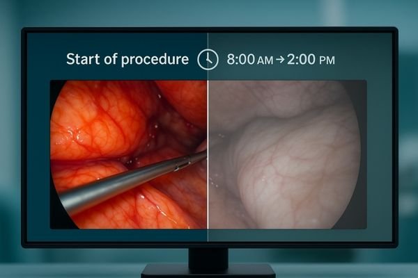
Hours into a complex procedure, the image on the main display seems faded. Critical anatomical details that were sharp and clear at the start are now washed out and harder to discern.
Intraoperative dimming is a gradual, often unnoticed drop in display luminance during long procedures. This guide covers how to measure it, its technical causes, and the verifiable solutions needed to ensure stable brightness.
- Executive summary: define dimming with objective curves, engineer closed-loop stabilization and sane ABL, and prove stability with logs for better outcomes and lower TCO.
In the operating room, consistency is paramount. A surgeon relies on a stable, predictable view to make critical decisions with confidence. However, over the course of a long and demanding surgery, a display’s brightness can slowly and silently degrade. This phenomenon, known as intraoperative dimming, is not just a minor annoyance; it is a critical failure of performance that can directly impact clinical efficacy and team efficiency. While often attributed to eye fatigue, the root cause is typically a combination of thermal stress, power management policies, and the lack of active stabilization in the display itself. Fortunately, this is not an unsolvable problem. By understanding the technical causes and implementing a verifiable system of controls, we can transform luminance stability1 from a subjective feeling into an objective, auditable, and reliable pillar of surgical imaging.
What intraoperative dimming is and how to measure it
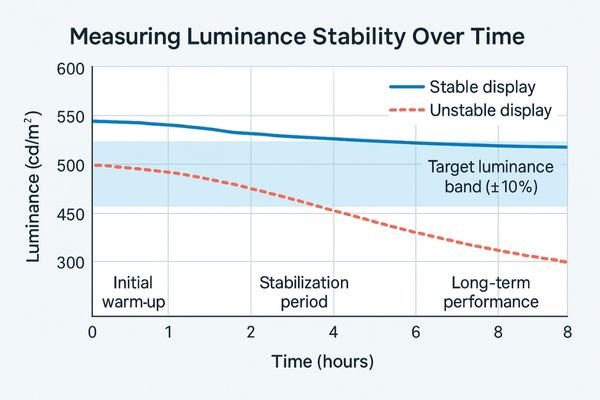
Move beyond perception: quantify luminance, contrast, and color stability at defined time points across an 8-hour session.
Intraoperative dimming is the measurable drop in luminance and contrast over time. It is quantified by recording time-based curves of light output, contrast, and color stability at set intervals.
Intraoperative dimming is the verifiable, gradual decrease or fluctuation in a display’s light output during a single, prolonged session. This is not a sudden failure but a slow degradation that subtly erodes image quality. As the luminance falls, the image loses "pop," and the distinction between the brightest whites and darkest blacks—the contrast ratio—diminishes. This can wash out highlights and make it harder to perceive subtle details in shadowed areas.
Objective measurement
To combat this, we must measure it. This involves using a photometer to capture performance data at key intervals. The process starts with a baseline measurement after the display has warmed up and stabilized. Then, subsequent measurements are taken at one, two, four, and eight-hour marks during continuous operation. Key metrics to track include:
- Luminance (L’max / L’min): The light output of peak white and minimum black.
- Contrast Ratio: The difference between L’max and L’min.
- White Point Drift2: Any change in the color temperature of pure white.
- Spatial Uniformity: The consistency of brightness across different areas of the screen.
By plotting these values over time, a clear performance curve emerges, turning a subjective complaint into actionable data.
Luminance stability test matrix (example)
| Timepoint | L’max (cd/m²) | L’min (cd/m²) | Contrast | White point drift (ΔK) | Uniformity (min/center %) | Pass/Fail | Notes |
|---|---|---|---|---|---|---|---|
| Warm-up (stabilized) | |||||||
| 1 h | |||||||
| 2 h | |||||||
| 4 h | |||||||
| 8 h |
Technical causes of dimming
Name the culprits early: thermal droop, ABL policies, missing stabilization, aging, airflow, and misconfigured modes.
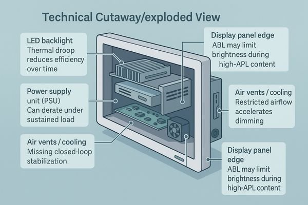
Common causes include backlight thermal droop, aggressive Automatic Brightness Limiting (ABL) policies, the lack of closed-loop stabilization, panel aging, and insufficient airflow, which collectively degrade performance under sustained load.
Several technical factors contribute to a display’s inability to maintain stable luminance over extended periods. Understanding these root causes is the first step toward building a reliable solution.
Thermal and power management issues
- Backlight Thermal Droop3: The LEDs that illuminate the display become less efficient as they heat up. During a long surgery, waste heat builds up, causing the LEDs’ light output to naturally decrease. Without a system to compensate, the screen will dim.
- Power Supply Derating: The power supply unit (PSU) can also overheat under sustained load, causing it to reduce its power output as a self-protective measure, which in turn reduces power to the backlight.
- Automatic Brightness Limiting (ABL): Many displays have aggressive ABL algorithms designed to manage power and heat. When the display shows a very bright, full-screen image for a long time (high Average Picture Level or APL), the ABL can automatically dim the backlight to prevent overload, even if it is not necessary.
Design and aging factors
Other causes include the absence of a closed-loop stabilization circuit to actively manage brightness, natural panel aging which reduces efficiency over thousands of hours, and poor environmental conditions like blocked airflow from improper mounting. Incorrectly configured "eco" modes can also artificially limit brightness.
Clinical impact: contrast loss, eye strain, slower reads
Tie image quality to human factors: reduced contrast raises cognitive load, increases misreads, and slows the case.
Falling luminance reduces contrast, hiding subtle cues and increasing glare. This forces surgeons to strain their eyes, change position, or request adjustments, slowing the procedure and increasing the risk of error.

A drop in display brightness4 is not just a technical footnote; it has tangible clinical consequences. As the luminance decreases, the image contrast is compressed. This makes it more difficult to distinguish between low-contrast tissues or see fine details hidden within shadows or bright areas. The perceived effect of glare from overhead surgical lights also becomes more pronounced against a dimmer background, further obscuring the image. The human response to this degradation is to compensate. Surgeons and nurses may find themselves leaning closer to the screen, straining their eyes to resolve details that were easily visible hours before. This not only causes physical discomfort and eye fatigue over a long case but also increases cognitive load, as the brain must work harder to interpret the compromised visual information. This can lead to slower reads, requests to adjust display settings mid-procedure, and breaks in concentration, all of which disrupt the flow of the surgery and can elevate the risk of misinterpretation or error.
Key takeaways
- Contrast loss hides low-contrast cues and makes glare more disruptive.
- Compensation behaviors (leaning in, adjusting settings) slow workflow and raise fatigue.
- Unpredictable dimming increases error risk and coordination overhead.
A verifiable solution: lock luminance for the entire case
Engineer determinism: active stabilization, sane ABL, good thermals, locked presets, and controlled setup with auditable logs.
The solution uses five pillars: closed-loop stabilization, a dedicated "Surgery Mode" without aggressive ABL, robust thermal design, locked calibration presets, and controlled environmental conditions for truly stable, case-long luminance.
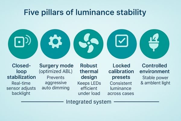
A truly stable display is the result of deliberate design and rigorous verification. A robust solution is built on five key pillars.
- Closed-Loop Stabilization: A front-facing or embedded sensor continuously measures the screen’s brightness and adjusts the backlight in real-time to maintain a calibrated target (e.g., 400–600 cd/m²) with a tight tolerance (e.g., ±10%) for the entire duration of the case.
- Optimized Power Management5: Use a dedicated "Surgery Mode" that disables or relaxes aggressive ABL so sustained high-APL content does not trigger unnecessary dimming.
- Robust Thermal Design: Engineer effective intake and exhaust, define standoff space for booms/walls, and specify filter cleaning intervals to maintain airflow.
- Unified Calibration and Presets: Calibrate luminance, color temperature, and gamma to a uniform preset; schedule quarterly auto-checks and annual multi-point tests with auditable logs.
- Controlled Environment and Power: Avoid stacking heat sources; maintain ambient 20–40 lux; ensure rated power/cabling to prevent PSU derating.
Acceptance checklist for procurement
- Stabilization sensor type and location; target luminance (e.g., 400–600 cd/m²) and stability tolerance (≤ ±10%).
- ABL policy in Surgery Mode; behavior under 100% APL full-field vs 10% window patterns.
- Thermal clearance guidelines for mounts/booms; filter maintenance schedule.
- Quarterly stabilization verification and annual multi-point reports (luminance, uniformity, white point) with timestamps and device IDs.
- Power and cabling specifications to avoid voltage drop/derating.
Recommended Surgical Displays for Stable Luminance
| Model | Category | Max luminance (cd/m²) | Stabilization sensor | Surgery-mode ABL | 8-hour retention target | Airflow clearance guide | Notes |
|---|---|---|---|---|---|---|---|
| MS322PB | Tower/Boom Main (4K) | Verify | Verify | Verify | Verify | Specify | Check stabilization policy and boom standoff space. |
| MS550P | Wall Team (4K) | Verify | Verify | Verify | Verify | Specify | Verify high-APL retention for team viewing. |
| MS192SA | Compact/Mobile (FHD) | Verify | Verify | —/Verify | Verify | Specify | Add quarterly self-checks; keep ducts clean. |
| MS270P | Teaching/Aux (FHD) | Verify | —/Verify | —/Verify | Verify | Specify | Include preset lock and power cable spec in acceptance. |
For specs or disinfectant whitelist, contact info@reshinmonitors.com.
Measurable business value
Map engineering controls to outcomes: fewer interruptions, faster cases, longer service life, and simpler audits.
Stable luminance cuts down on interruptions and re-reads, which shortens case times. It also reduces downtime from thermal wear and speeds up audits with verifiable logs, ultimately lowering the total cost of ownership.
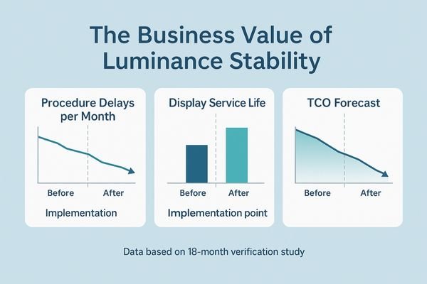
The business case for displays with verifiable luminance stability is compelling. Operationally, a stable and predictable image reduces the small hesitations, re-reads, and mid-procedure adjustment requests that collectively add time to every long case. This contributes to more efficient OR utilization and higher throughput. Financially, the benefits are significant. Robust thermal management and the prevention of constant thermal derating reduce stress on the backlight and power components, leading to fewer failures, less downtime for repairs, and a longer overall service life for the asset. This extends the replacement cycle and preserves capital. Furthermore, the ability to produce auditable logs of luminance performance simplifies quality assurance, speeds up acceptance testing, and provides concrete data for compliance and audits. These factors combine to create a lower, more predictable total cost of ownership (TCO).
FAQ
How long should it take for a display to stabilize?
A medical display will typically warm up to a usable brightness in a few minutes. However, it may take 15 to 30 minutes for the closed-loop stabilization system to fully converge on its target luminance. After this initial period, the brightness should remain stable for the remainder of the case.
Action: log time-to-stability and target tracking in the QA record.
How can I tell if dimming is from ABL or a thermal issue?
You can test this by using different patterns. If the display only dims when showing a full-field white image but remains bright with a smaller white window pattern, the cause is likely an aggressive ABL policy. If the display dims with both patterns and its surface temperature is rising, the root cause is more likely a thermal issue.
Action: test full-field vs 10% window, record chassis temperature and luminance curves.
What is a reasonable calibration cadence?
A good practice is a three-tiered approach. A quick daily self-check can be run by the system automatically. A more thorough verification of the stabilization system should be performed quarterly. A comprehensive, multi-point test of luminance, uniformity, and white point, with auditable logs, should be conducted annually.
Action: include cadence and reporting format in procurement and maintenance contracts.
Do this now (3 steps)
- Run an 8-hour luminance stability test and fill the matrix with results.
- Enable Surgery Mode (relaxed ABL) and verify behavior under full-field and window patterns.
- Ensure airflow clearance on mounts/booms and document quarterly/annual checks with logs.
Conclusion
With closed-loop control, intelligent ABL, solid thermal design, and locked presets, you can turn luminance stability from a subjective feeling into consistent, auditable data for the entire surgical case. 💡
👉 For expert insights and Reshin’s luminance-stable surgical display solutions, contact info@reshinmonitors.com.
-
Exploring luminance stability solutions can enhance surgical imaging reliability, leading to better decision-making in the operating room. ↩
-
Exploring White Point Drift helps in maintaining color accuracy, essential for professional visual work. ↩
-
Understanding Backlight Thermal Droop is crucial for improving display performance and longevity. ↩
-
Understanding the impact of display brightness on surgical performance can help improve outcomes and reduce errors. ↩
-
Exploring Optimized Power Management will provide insights into energy efficiency and device longevity, crucial for modern technology. ↩