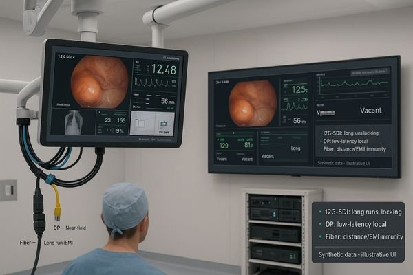
In the operating room, a single dropped video frame or excessive latency can disrupt a surgeon’s hand-eye coordination. Outdated or poorly chosen cabling creates these risks, compromising procedural safety.
Zero-frame-drop OR video demands deterministic transport and hard numbers. Use 12G-SDI for locked long runs, DP for near-field low latency, and fiber for distance. Prove it: glass-to-glass ≤50 ms typical (≤80 ms worst) and zero observed drops during a 15-minute stress test with source switches and multiview. Hybrid done right beats distance, EMI, and chaos.
The promise of "real-time" video in a surgical setting is not just a feature; it is a fundamental requirement for patient safety. As resolutions climb to 4K60, the technical challenge of delivering every single frame without fail and with minimal delay becomes immense. This is not a task for consumer-grade solutions. Achieving a truly zero-frame-drop environment1 requires a deep understanding of video transport technologies, a disciplined approach to system design, and rigorous, objective measurement. This guide outlines a road-tested methodology for evaluating and deploying a hybrid video infrastructure that is robust, reliable, and ready for the demands of the modern OR.
Zero-frame-drop defined & the latency budget at 4K60
The term "real-time" is often used loosely in marketing materials. This ambiguity is dangerous in a clinical setting, where a few milliseconds of delay can have tangible consequences for the surgeon.
"Zero-frame-drop" at 4K60 means never missing a single 16.7 ms frame. The entire glass-to-glass latency budget should be under 80 ms to remain below the threshold of human perception for surgical tasks.
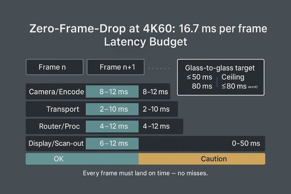
Achieving a "zero-frame-drop2" environment at a 4K resolution with a 60Hz refresh rate is a demanding technical standard. It means that the entire video chain—from the camera sensor to the pixels on the display—must successfully deliver every single frame within its 16.7-millisecond window, without exception, even under full operational load. Alongside this, we must manage latency, which I treat as a strict budget. This end-to-end, or "glass-to-glass3," latency is the sum of delays from every component: source encoding, signal transport, switcher or router processing, and finally, the display’s own scan-out time. In the OR, surgeons’ hand-eye coordination can be perceptibly affected by delays exceeding approximately 60 to 80 milliseconds. Therefore, a safe and robust system should target a typical latency of 50 ms or less, with a worst-case a ceiling of 80 ms. A high-performance surgical monitor like the MS322PB, with its low-latency processing modes, is a critical component in meeting this budget. These figures cannot be taken from vendor slideshows; they must be proven with objective, repeatable measurements.
12G-SDI vs DisplayPort vs Fiber: what each guarantees (and what it doesn’t)
Choosing a video interface is not about picking the "best" one. Each technology was designed for a different purpose, and using the wrong one for the job introduces unnecessary risk.
12G-SDI offers locked, long-distance reliability. DisplayPort provides low-latency local connections. Fiber reigns supreme over extreme distances. A successful system uses each where its strengths lie.
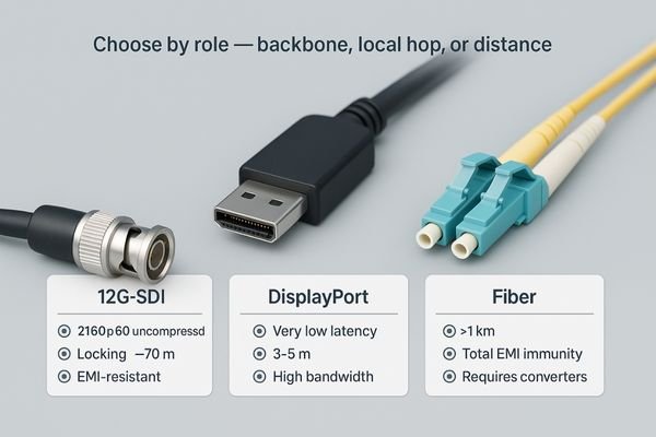
Understanding what each cabling standard guarantees is crucial to building a resilient system. 12G-SDI is the workhorse for professional video. It guarantees a deterministic, uncompressed 2160p60 signal over tens of meters of coaxial cable, features robust locking BNC connectors that resist vibration and accidental disconnection, and offers good immunity to electromagnetic interference (EMI). DisplayPort (DP) is a packet-based standard excellent for high-bandwidth, very low-latency connections over short distances, making it ideal for connecting a source directly to a monitor on a surgical boom or tower. However, it is less tolerant of marginal quality cables and can be susceptible to hot-plugging issues. Fiber optics4 is the undisputed king of long-distance transport, capable of sending signals for kilometers with perfect EMI immunity. Whether using SDI-to-fiber or DP-over-fiber extenders, it solves distance problems, but introduces potential failure points at the converter modules and can be sensitive to clocking and EDID (Extended Display Identification Data) quirks that may add latency. A monitor like the MS321PB with multiple native inputs including 12G-SDI5 and DP provides the flexibility to leverage these different transport methods effectively within a single OR.
| Interface | Best Use Case | Max Distance (Typical) | Key Strengths | Potential Weaknesses |
|---|---|---|---|---|
| 12G-SDI | OR backbone, long runs | ~70 m | Locking connector, robust, EMI resistant | Higher component cost |
| DisplayPort | Local connection (boom/tower) | 3–5 m | Very low latency, high bandwidth | Non-locking, distance limited |
| Fiber Optic | Inter-room, noisy pathways | > 1 km | Extreme distance, total EMI immunity | Requires converters, adds complexity |
How to measure in the OR: glass-to-glass latency & frame-drop detection
You cannot manage what you cannot measure. Relying on a subjective feeling of "smoothness" is not a valid method for verifying a mission-critical video system in the operating room.
Use a high-speed camera and a source with a timecode overlay to measure glass-to-glass latency. A scrolling bar test pattern will instantly and objectively reveal any dropped frames during stress testing.
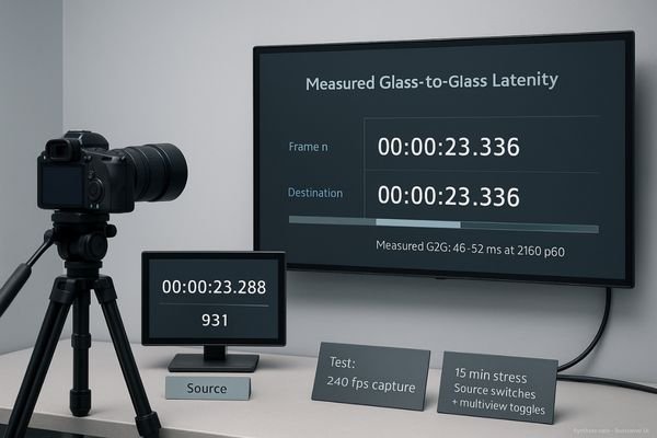
Subjective assessments are insufficient for system validation. Objective measurement is mandatory. To measure glass-to-glass latency6, a proven method involves feeding the system a video source that has a running timecode or millisecond counter burned into the image. Then, a high-speed camera (filming at 240 fps or higher) is used to simultaneously record the source monitor and the destination display. By analyzing the captured video frame-by-frame, it is possible to count the exact difference in the timecode, revealing the true end-to-end latency. For frame-drop detection7, a simpler but equally effective method is to use a test pattern generator that creates a smooth, continuously scrolling bar or a frame counter. Any dropped frames will cause a visible jump or stutter in the pattern, which is immediately obvious to the naked eye and easily captured on video. These tests should not be run on an idle system. The most revealing tests are 10-to-15-minute stress runs that involve actively switching sources, toggling multiview modes on a display like the MS550P, and even unplugging and replugging non-critical cables. Failures are most likely to occur during these mid-procedure events, not during a static loop.
A hybrid wiring recipe that survives distance, EMI, and failover
A single-interface approach is a brittle one. A system that relies entirely on DisplayPort will fail at long distances, while one that is only SDI may lack the lowest latency for near-field monitors.
A durable hybrid approach uses 12G-SDI for the primary backbone, DisplayPort for local low-latency hops, and fiber for runs over 30-50 meters or through noisy areas, with built-in redundancy.
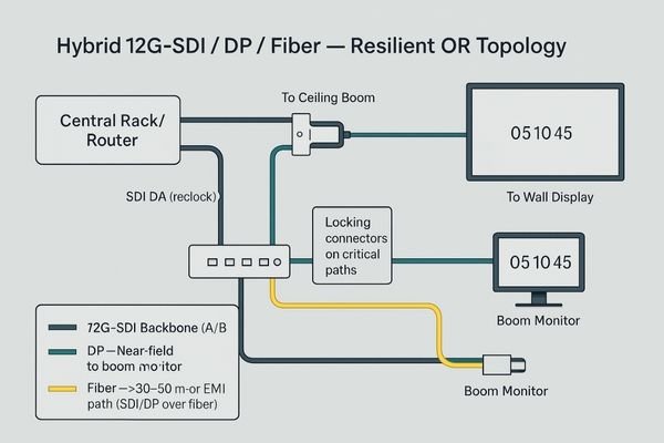
A resilient OR video system is a hybrid one, leveraging the best of each technology. A durable recipe for success starts with 12G-SDI8 as the primary video backbone. Use it for all long runs from the central equipment rack or router to the surgical booms and wall displays. Its locking connectors and signal integrity make it the most reliable choice. For local, near-field connections—such as from a device on a boom to its dedicated monitor—use short, high-quality DisplayPort cables9 to achieve the absolute lowest latency. For any connection that needs to cross more than 30 to 50 meters, or must pass through an area with high EMI (such as near an electrosurgical unit’s power lines), use fiber optic extenders. This architecture should be designed with redundancy in mind, such as running A/B signal paths to critical displays. Where possible, use SDI distribution amplifiers with reclocking to regenerate the signal on long runs. For legacy or ancillary equipment that may only have Full HD outputs, a cost-effective monitor like the MS270P with 3G-SDI and mixed digital/analog inputs provides an easy integration point without compromising the main 4K infrastructure. This layered, hybrid approach is the best defense against distance, interference, and human error.
Pass/fail thresholds and a deployment checklist
Without clear, predefined criteria, system acceptance can become a subjective and endless debate. A blunt, data-driven pass/fail threshold is essential for a successful deployment and handover.
The pass/fail criteria are straightforward: zero observed frame drops during a 15-minute stress test, and measured end-to-end latency that remains within the predefined budget under all test conditions.
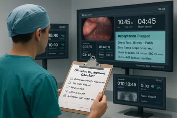
The final acceptance of the system must be based on hard data, not opinion. The pass/fail criteria should be blunt and agreed upon before testing begins. The primary requirement is zero observed frame drops10 during a scripted 15-minute stress test that simulates a complex procedure. This script must include multiple source switches, activation of PIP/PBP multiview modes, and any other functions that will be used clinically. The secondary requirement is that the measured glass-to-glass latency11 must remain within the defined budget (e.g., ≤50 ms typical, ≤80 ms max) across all tested configurations. This validation process must be meticulously documented. This documentation is the system’s "birth certificate" and is critical for future troubleshooting and maintenance. It proves that the "zero-drop" claim is not just a marketing slogan but a verified reality of the installation. For simpler, local connections with legacy equipment, a monitor like the MS220SA with its broad compatibility can be validated with the same rigor for its specific role.
Deployment Validation Checklist
- All cable types and lengths documented.
- SDI equalization/reclocking settings recorded.
- Display EDID settings verified for all sources.
- Performed 15-minute frame-drop stress test (Result: PASS/FAIL).
- Measured glass-to-glass latency for primary paths (Result: In/Out of Budget).
- Tested failover and redundant path switching.
- Confirmed physical security of all locking connectors.
- Final system schematic updated to as-built state.
Conclusion
A zero-frame-drop, low-latency OR video system is achieved through disciplined engineering, hybrid design, and rigorous, objective testing—not by relying on a single technology or brand. 🎥
👉 For expert insights and Reshin’s OR video display solutions, contact martin@reshinmonitors.com.
-
Learn about the technologies and methodologies that ensure seamless video delivery, crucial for high-stakes surgical procedures. ↩
-
Understanding zero-frame-drop is crucial for achieving optimal video performance, especially in high-stakes environments like surgery. ↩
-
Exploring glass-to-glass latency helps in grasping the importance of minimizing delays in video systems for critical applications. ↩
-
Learn how fiber optics enhances data transmission over long distances, ensuring reliability and performance. ↩
-
Explore the advantages of 12G-SDI to understand its role in delivering high-quality video signals. ↩
-
Understanding glass-to-glass latency is crucial for optimizing video systems. Explore this link to learn about measurement techniques and best practices. ↩
-
Frame-drop detection is vital for maintaining video quality. Discover effective methods and tools to ensure seamless playback by visiting this resource. ↩
-
Explore this link to understand how 12G-SDI enhances video quality and reliability in surgical environments. ↩
-
Learn about the benefits of DisplayPort cables for low latency connections, crucial for high-performance video systems. ↩
-
Explore this link to understand how to achieve zero frame drops, ensuring your system meets critical performance standards. ↩
-
This resource will guide you on measuring and optimizing latency, crucial for maintaining high-quality video performance. ↩