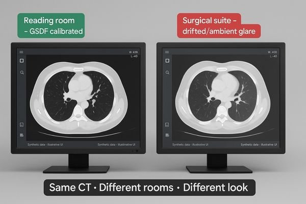
A radiologist views a CT scan, but the image in the reading room looks different from the one in the surgical suite. This inconsistency creates diagnostic uncertainty and workflow friction.
The same CT study should present the same grayscale—room to room. If it doesn’t, the issue isn’t the scan; it’s the display pipeline: calibration, luminance stability, signal path, and ambient light. This guide maps the risks and a practical, auditable fix—GSDF calibration, stabilized luminance, 20–40 lux reading rooms, matched viewer presets, and routine QA—so one CT has one look everywhere.
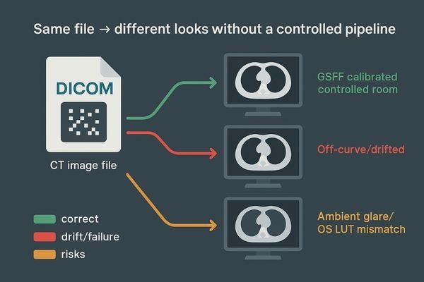
When a CT image file is sent to two different displays, the expectation is that they will look identical. However, the reality is often quite different. The path from digital pixel value to the light emitted by a monitor is complex and filled with variables that can alter the final image. This is not about the CT scanner or the reconstruction algorithm; this analysis assumes the source data is identical. The problem lies squarely in the display pipeline1—the combination of hardware, software, and environmental factors that translate data into a visible image. Understanding this variability is the first step toward building a reliable and reproducible viewing environment2.
Beyond the Source File
The core of the issue is that the image file itself is just a set of numbers. The display system’s job is to translate these numbers into a visually accurate representation. This translation process is where a multitude of errors can be introduced. Many institutions invest heavily in high-end imaging modalities but overlook the final, critical step of display. They may assume that any "medical grade" monitor will suffice, without realizing that factors like calibration3, luminance stability, and ambient light create significant deviations. By systematically addressing each point of failure in this pipeline, we can create a deterministic system where the image presented is a true and consistent representation of the source data, regardless of the room it is viewed in.
What “same CT, different look” really means
The same digital file can produce vastly different visual interpretations on separate screens. This isn’t just a minor annoyance; it’s a fundamental breakdown in image reproducibility.
This issue is a perceived grayscale difference in the same CT study across rooms, assuming identical source data. It stems from the display and rendering path, not the underlying image file.
The problem of a "different look" is specifically about the inconsistency in how grayscale values4 are rendered. We begin by assuming the source data—the reconstructed CT study—is identical and that the same window and level settings are applied. The discrepancy arises during the display process, where the numerical pixel values are translated into light. On one monitor, subtle low-density lesions5 might be clearly visible, while on another, they are lost in the noise or merged with surrounding tissue. On a third display, the image might appear sharper but with crushed blacks, obscuring details in darker regions.
A Failure of Reproducibility
This is not a problem with the file itself; it is a failure of the visualization pipeline6 to be deterministic and reproducible. The screen in the primary reading room renders grays differently than the one in the on-call room, the conference room where tumor boards meet, or at a referring physician’s office. This variability breaks the visual contract that what one clinician sees, another will see as well. It introduces a dangerous element of subjectivity into what should be an objective process. It transforms a precise, data-driven image into an unreliable representation, fundamentally undermining the basis of consistent radiological interpretation7 and long-term patient follow-up.
Why it matters: clinical, workflow, and compliance risks
When image displays are inconsistent, clinicians start to doubt what they see. This hesitation can lead to delayed diagnoses and requests for unnecessary follow-up scans to confirm findings.
Inconsistent rendering changes lesion visibility, undermines comparisons with prior studies, increases repeat scans and reading times, and elevates medico-legal risk due to potential diagnostic errors.
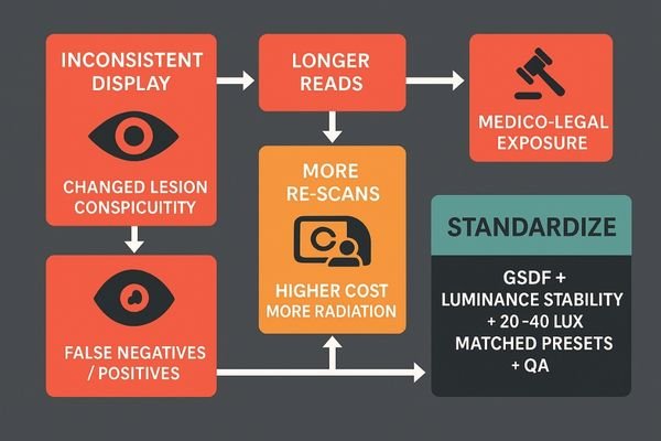
The clinical implications of inconsistent display performance are significant. The conspicuity of a lesion—its visibility against the background anatomy—is highly dependent on precise grayscale rendering8. A monitor that deviates from the standard can either mask a subtle finding or create a visual artifact that mimics pathology, leading to both false negatives and false positives9. This variability critically undermines prior-to-current comparisons, which are essential for tracking disease progression or treatment response.
The Ripple Effect of Inconsistency
From a workflow perspective, this uncertainty inflates reading times as radiologists10 spend longer manipulating window and level settings to compensate for a poor display. It also leads to more requests for repeat scans, increasing patient radiation exposure and operational costs. For compliance, the lack of a standardized and documented viewing environment introduces significant medico-legal exposure11. In the event of a diagnostic dispute, the inability to prove that the viewing conditions met established standards can weaken an institution’s defensibility. This creates a ripple effect where a technical issue cascades into clinical inefficiency, increased operational costs, and elevated legal risk for the entire organization.
Root causes: technology, workflow, and environment
Many assume a professional display will "just work" out of the box, year after year. The reality is that displays are complex devices that drift over time and are affected by their surroundings.
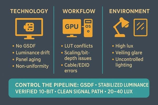
Root causes include a lack of DICOM calibration, luminance instability, panel aging, software mismatches, signal path issues, and uncontrolled ambient light, creating a web of interconnected problems.
The problem of inconsistent rendering stems from an interdependent mix of technology, workflow, and environmental factors.
Technological Drift and Degradation
The most common culprit is the absence of calibration to the DICOM Part 14 Grayscale Standard Display Function (GSDF)12. Without this, there is no guarantee that pixel values will be rendered with perceptually linear steps. Furthermore, a lack of luminance stabilization means the display’s brightness and black level can drift due to panel aging, temperature changes, and warm-up time. Uniformity issues can also cause the center of the screen to look different from the edges.
Procedural and Workflow Gaps
Workflow issues contribute significantly. Mismatches between the graphics card (GPU) settings, operating system scaling, and viewer software can corrupt the lookup table (LUT)13 that governs grayscale. Signal path integrity is another factor, where poor quality cables or EDID handshake failures can compromise the image.
The Environmental Factor
Uncontrolled ambient light and veiling glare from reflections on a screen can dramatically reduce effective contrast, washing out subtle details and making it impossible to discern fine textures or low-contrast lesions.
| Category | Root Cause Example | Impact on Image |
|---|---|---|
| Technology | Panel aging and backlight degradation | Reduced maximum brightness and altered contrast ratio. |
| Workflow | GPU or OS color management overrides | Non-standard gamma curves applied, distorting grayscale. |
| Environment | High ambient light in the reading room | Washes out dark details and reduces perceived contrast. |
Solution framework: make grayscale deterministic
Simply buying a high-quality monitor is not a solution. The entire imaging pipeline from the graphics card to the observer’s eye must be managed and controlled to achieve consistency.
A deterministic pipeline is the goal. This requires stabilized luminance, GSDF-mapped grayscale, a controlled lighting environment, matched viewer presets, and documented quality assurance protocols.
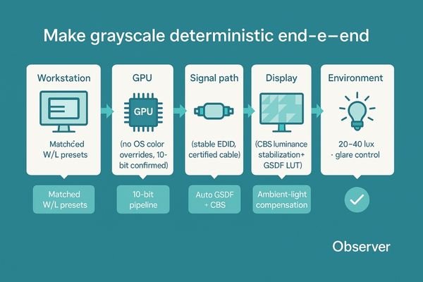
The solution is to build a deterministic display pipeline, where every step in the rendering process is controlled, measured, and predictable. This framework moves beyond simply purchasing a diagnostic monitor; it involves creating a holistic system that ensures reliability from pixel to perception.
The Principles of a Controlled Pipeline
The foundation is a display with stabilized luminance14, ensuring the monitor’s brightness and black levels remain constant over time, and a grayscale response that is meticulously mapped to the DICOM GSDF. Reading rooms should maintain low ambient light levels (ideally 20–40 lux) to prevent glare and preserve on-screen contrast. On the software side, viewer presets and window/level settings must be standardized and locked across all workstations to eliminate user-introduced variability. Finally, this entire system must be underpinned by a documented quality assurance (QA) program15 with defined tolerances and logs.
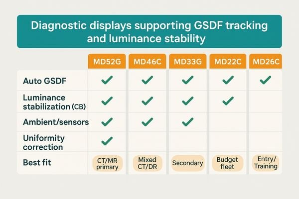
Recommended diagnostic displays (CT/MR primary & secondary reads)
Five concise options that directly support GSDF tracking, luminance stability, and uniformity control.
| Model | Auto GSDF / LUT | Luminance Stabilization (CBS) | Ambient / Sensors | Uniformity Correction | Best Fit |
|---|---|---|---|---|---|
| MD52G | ✓ | ✓ | ✓ | ✓ | CT/MR primary reads, long-hour stability |
| MD46C | ✓ | ✓ | ✓ | ✓ | Mixed CT/DR/PACS; balanced TCO |
| MD33G | ✓ | ✓ | – | ✓ | Secondary reads, compact bays |
| MD32C | ✓ | – | – | ✓ | Standardized fleets, budget control |
| MD26C | ✓ | – | – | ✓ | Entry diagnostic rooms, training labs |
Quick implementation checklist
- Target luminance/black level set and locked (e.g., 350 cd/m² white, ≤0.5 cd/m² black; tune per policy).
- GSDF calibration verified end-to-end; eliminate OS/GPU/viewer LUT conflicts.
- 10-bit pipeline confirmed (source → GPU → cable → display); EDID stable.
- Ambient light controlled (20–40 lux reading room); veiling glare mitigated.
- Window/level presets standardized across workstations; user overrides minimized.
- QA schedule in place (warm-up policy, periodic checks, drift thresholds, logging).
Implementation: step-by-step to lock consistency
Achieving display consistency seems daunting, but it can be broken down into a methodical process. A structured implementation plan ensures that no variable is left uncontrolled.
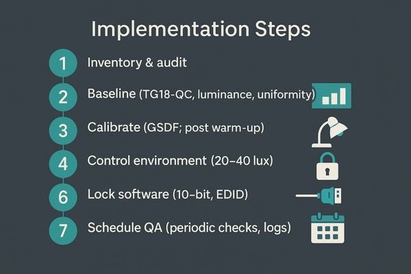
Implementation involves inventorying all displays, establishing a performance baseline, calibrating to DICOM standards, controlling the environment, locking software presets, and scheduling regular QA checks.
A Phased Approach to Standardization
- Inventory & audit: catalog displays, GPUs, cables, viewers; flag outliers.
- Baseline: measure with TG18-QC; record luminance, contrast, grayscale tracking.
- Calibrate: apply GSDF with target white/black; verify after warm-up.
- Control environment: set 20–40 lux; fix glare and blinds; document.
- Lock software: standardize window/level presets; manage permissions.
- Verify pipeline: confirm 10-bit; stable EDID; no OS/GPU color overrides.
- Schedule QA: periodic checks for JND/ΔL/L/uniformity; keep logs.
Evidence & benchmarks: how to prove it works
Simply stating that displays are calibrated is not enough. A robust quality assurance program requires objective evidence and clear benchmarks to prove compliance and effectiveness over time.
Proof of consistency comes from objective data. This includes before-and-after photometer readings, Just-Noticeable Difference (JND) tracking, and uniformity logs against defined thresholds.
From Subjective Opinion to Objective Data
Use a calibrated photometer to record luminance, contrast ratio, and GSDF tracking before/after calibration. Track JND index over time to spot drift; measure ΔL/L and spatial uniformity to ensure consistency across the screen. Compare all results to acceptance targets and keep signed logs for audits.
| Metric (after calibration) | Acceptance target | Notes |
|---|---|---|
| JND index (GSDF tracking) | < 10 | Lower is better; track drift over time |
| Luminance stability (ΔL/L) | ≤ 10% | After warm-up; verify CBS holds |
| Spatial uniformity (max dev) | ≤ 15% | Center vs. corners/edges |
| Contrast ratio (typical) | ≥ 1000:1 | Mode-dependent; document method |
| Ambient light (reading room) | 20–40 lux | Log during QA runs |
FAQ: practical questions from radiology teams
Q: Do I need 4K to fix this?
A: No. Consistency beats pixels. A calibrated 2MP with GSDF and stability is preferable to an uncalibrated 4K.
Q: How often should we recalibrate?
A: Base it on usage and drift data. Modern stabilized diagnostics may need periodic verification; legacy/high-use units often require quarterly checks.
Q: Can lower-cost clinical displays suffice for review?
A: Only if they can meet and maintain target luminance/black, track GSDF, and operate under controlled ambient light—sustained over time.
Q: Does window/level replace calibration?
A: No. Calibration standardizes the canvas; window/level is how you interrogate data on that calibrated foundation.
Q: What’s the quickest self-check for a “different look” room?
A: View TG18-QC: if visible grayscale steps differ by >2 levels vs. the reading room, or blacks look lifted/crushed, you likely have a pipeline or ambient issue.
Conclusion: one CT, one look—every room
By standardizing GSDF calibration, stabilizing luminance, controlling ambient light, and locking software presets with ongoing QA, institutions can ensure that the same CT study looks the same in every room—protecting diagnostic confidence, efficiency, and defensibility. For a site-wide deployment checklist or demo units, contact info@reshinmonitors.com.
-
Explore this link to understand how the display pipeline affects image quality and consistency across different monitors. ↩
-
This resource will provide insights on establishing a consistent viewing environment, crucial for accurate image interpretation. ↩
-
Exploring calibration’s role can help ensure your imaging systems deliver the best possible results. ↩
-
Understanding grayscale values is crucial for interpreting images accurately, especially in medical imaging. ↩
-
Exploring how low-density lesions are identified can enhance your knowledge of diagnostic imaging techniques. ↩
-
Understanding the visualization pipeline is crucial for ensuring consistent and accurate data representation across different platforms. ↩
-
Exploring this topic reveals the importance of accurate imaging in diagnosis and treatment, which is vital for patient outcomes. ↩
-
Understanding grayscale rendering is crucial for improving diagnostic accuracy and ensuring effective disease tracking. ↩
-
Exploring this topic helps clarify the risks of misdiagnosis and the importance of accurate display performance. ↩
-
Understanding the challenges radiologists face can help improve workflows and patient care. ↩
-
Exploring this topic can provide insights into legal risks and compliance strategies for healthcare organizations. ↩
-
Understanding GSDF is crucial for ensuring accurate medical imaging and display calibration, enhancing diagnostic accuracy. ↩
-
Exploring LUTs will help you grasp their role in image processing, crucial for maintaining image quality and consistency. ↩
-
Understanding stabilized luminance is crucial for maintaining consistent display quality in medical imaging. ↩
-
Exploring QA programs helps ensure high standards in medical imaging, enhancing patient safety and diagnostic accuracy. ↩