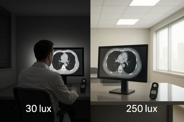
A radiologist squints at a perfectly calibrated monitor, yet subtle lung nodules remain indistinct. The problem is not the display, but the uncontrolled light in the room, silently sabotaging the diagnosis.
Harmful ambient light raises a display’s effective black via glare and reflections, compresses near-black detail, and can negate GSDF calibration—quietly eroding diagnostic confidence.
In radiology, display calibration is rightly seen as a cornerstone of diagnostic accuracy. We invest significant resources to ensure our monitors adhere to the DICOM Grayscale Standard Display Function (GSDF)1. However, this effort is rendered almost meaningless if the viewing environment is not equally controlled. The silent battle between ambient lighting2 and monitor calibration is one that lighting almost always wins. A perfectly calibrated screen placed in a poorly lit room is a compromised tool. The human visual system adapts to the brightest sources in its field of view, and when uncontrolled light from windows, overhead fixtures, or reflections dominates, our ability to perceive subtle, low-contrast details on the screen is dramatically reduced. This article will explore how to define and identify harmful ambient light, explain the mechanisms by which it undermines even the best displays, and provide a systematic approach to synchronize the room and the monitor to win this battle and protect diagnostic integrity.
Defining harmful ambient light in reading rooms
Not all light is bad, but uncontrolled light is always a threat. Harmful ambient light is any light that interferes with the perception of a diagnostic image.
Harmful ambient light causes veiling glare or specular reflections that raise the effective black level, making it impossible for a GSDF-calibrated display to render low-contrast details accurately.
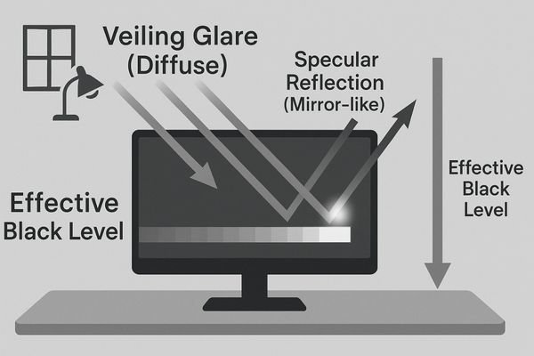
Harmful ambient light in a reading room is defined by its effect on the diagnostic image, not just its brightness. It becomes detrimental when it degrades the on-screen contrast to the point where clinical information is lost. This degradation occurs primarily through two mechanisms: veiling glare3 and specular reflections4. Veiling glare is a diffuse wash of light across the screen that elevates the display’s effective black level. It makes dark grays indistinguishable from true black, compressing the crucial near-black steps of the grayscale. Specular reflections are direct, mirror-like images of light sources (like a window or an overhead light) on the screen’s surface, which can create false edges or completely obscure the underlying anatomy.
The Red Flags of Poor Lighting
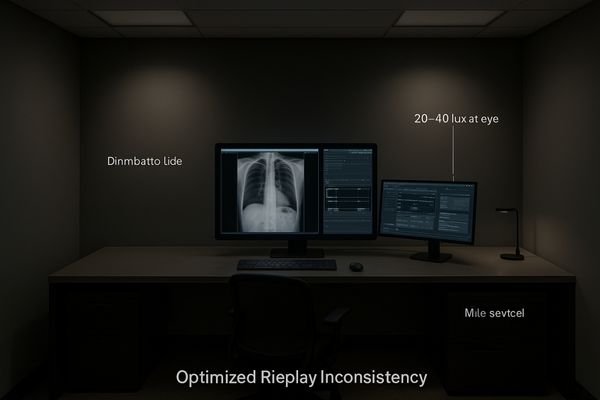
Typical red flags for a harmful environment include an illuminance level5 at the reader’s eye position above the recommended ~20–40 lux range, bright backgrounds or walls directly behind or beside the displays, glossy desk surfaces, and task lights aimed improperly at the screen. Even a monitor with flawless GSDF calibration6 will appear "washed out" in these conditions because the room’s lighting forces the radiologist’s visual system to adapt to a higher baseline brightness, rendering it insensitive to the subtle luminance differences that define low-contrast lesions.
How poor lighting undermines calibrated monitors
A calibrated display presents a mathematically precise image. Poor lighting forces the human eye to perceive a distorted, unreliable version of that image.
By elevating black levels, poor lighting compresses near-black grayscale steps, masks subtle findings, alters perceived color temperature, and increases eye strain, leading to slower, less consistent reads.
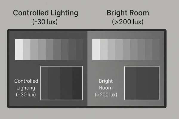
The primary way poor lighting undermines a calibrated monitor is by destroying its effective contrast ratio7. Calibration meticulously sets the display’s minimum luminance (Lmin) to produce deep, true blacks. Ambient light adds its own luminance to the screen via reflections, effectively raising this Lmin. As a result, the darkest steps of the GSDF curve are compressed and become indistinguishable from one another. This directly impacts clinical work by masking subtle findings like faint ground-glass opacities or low-density abnormalities in soft tissue. It also breaks the consistency of prior-to-current comparisons; a lesion’s conspicuity can change simply because the room lighting was different between the two reading sessions.
Beyond Grayscale: Color and Fatigue
Reflections don’t just wash out images; they can also create visual artifacts8 like false edges that mimic pathological signs. For color displays, mixed-temperature ambient lighting9 (e.g., cool daylight from a window combined with warm artificial light) can shift the perceived white point of the display, altering the appearance of tissue tones in digital pathology or endoscopy. The workflow consequences are significant: readers slow down, re-check their findings more often, and their interpretations are more likely to diverge. This hurts report consistency, complicates multidisciplinary team (MDT) consensus, and reduces patient throughput. Finally, the constant battle against glare leads to significant eye strain, shortening productive reading sessions.
Why it happens: room, display, and software factors
This problem is systemic, arising from a failure to align the room, the display technology, and the software into a cohesive viewing ecosystem.
It happens due to high-reflectance room surfaces and poor lighting control, display aging without stabilization, and inconsistent software presets or LUT conflicts across workstations.
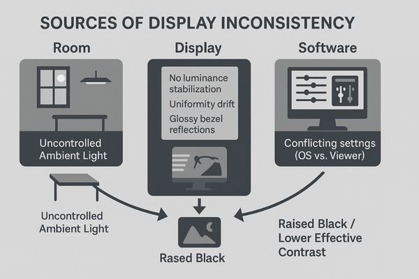
The battle between lighting and calibration is lost on three fronts: the room, the display, and the software.
The Hostile Environment
First, the room itself is often the primary antagonist. High-reflectance, light-colored paints on walls, uncovered windows allowing variable daylight, bright overhead fluorescent lights, and even illuminated signage can flood the environment with uncontrolled light. Task lights, while intended to be helpful, are often improperly positioned, pointing directly at the screen and creating intense specular reflections10.
Hardware and Software Vulnerabilities
Second, the display hardware contributes to the problem. Panels without active luminance stabilization11 are vulnerable to aging, where their brightness and contrast naturally drift over time, making them even more susceptible to being overpowered by ambient light. Poor screen uniformity can create brighter and darker zones, which are exacerbated by reflections. Even the physical design, such as glossy plastic bezels, can create distracting reflections. Third, software inconsistencies create a moving target. Different PACS viewer presets12, lookup table (LUT) conflicts between the operating system and the viewing application, and inconsistent gamma or white point settings between workstations mean that no two setups behave identically. Without a shared, enforced baseline, these tiny differences in each domain accumulate until they manifest as a visible and clinically significant drift.
How to test: lights-on/lights-off protocol
You cannot fix what you cannot measure. A simple, repeatable testing protocol can objectively quantify the impact of ambient light on diagnostic displays.
Use a "lights-on/lights-off" protocol: establish a baseline in a dark room, then turn on the lights and measure the degradation of near-black steps, Lmin, and uniformity.
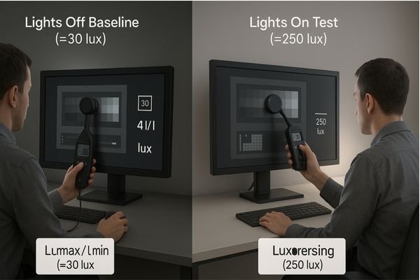
To quantify the impact of ambient light, a "lights-on/lights-off13" protocol provides clear, objective evidence. The process is methodical. First, prepare the system by matching software presets across workstations and allowing the displays a full 20–30 minute warm-up period to stabilize. The test begins with the lights off to establish a perfect-world baseline. Using a calibrated lux meter14, measure the illuminance at the user’s eye position and at the screen plane to confirm the room is dark. Then, run standardized test patterns like the AAPM TG18 or TG270 suite and use a photometer to record the display’s maximum and minimum luminance (Lmax/Lmin), calculate its stability (ΔL/L), and map its multi-point uniformity.
Quantifying the Degradation
Next, execute the "lights-on" portion of the test. Turn on the normal room lighting without moving the test equipment or the "eye box" position. Repeat the measurements. Critically, compare the visibility of the low-contrast and near-black grayscale steps15 between the two lighting states. The degradation will be immediately visible and quantifiable. For color-critical work, verify the white point and gamut16 in both states. For live video systems, check latency. Logging these paired results builds an undeniable, auditable baseline that demonstrates precisely how much the room’s lighting is compromising the calibrated performance of the display, providing the data needed to justify corrective actions.
Practical fixes: synchronize lighting and calibration
Winning this silent battle requires a two-pronged strategy: aggressively control the light in the room, and intelligently manage the light from the monitor.
Control room illuminance to ~20–40 lux with dimmable, neutral sources and matte surfaces. Standardize displays with GSDF calibration, luminance stabilization, and automated QA to create a unified system.
The solution is to synchronize the environment and the technology. First, take control of the room’s lighting. The goal is to achieve a consistent, low level of ambient illuminance17, ideally between 20 and 40 lux, at the radiologist’s viewing position. This is accomplished using dimmable, neutral-temperature (approaching D65 white point) light sources. Install blackout blinds or dual-layer shades on all windows to eliminate variable daylight. Paint walls with low-reflectance, matte, neutral gray paint. Replace glossy desks and furnishings with non-reflective alternatives. A highly effective technique is to use bias or back lighting—a dim, neutral light source placed behind the monitors—to create a gentle glow on the wall. This helps stabilize the user’s visual adaptation and reduce eye strain without creating on-screen glare.
Standardizing the Technology
Next, standardize the display pipeline. Deploy monitors that feature built-in luminance stabilization18 and uniformity correction. Enforce a single GSDF calibration standard across the entire fleet. Lock down technical settings like EDID, bit-depth, and viewer presets on every workstation to eliminate software-driven variability. The capstone of this strategy is an automated Quality Assurance (QA) system that continuously monitors display performance against defined thresholds and generates alerts for any deviation. This proactive approach ensures that drift is identified and corrected long before it becomes visually apparent to a clinician.
Recommended Diagnostic Monitors
| Model | Primary Use Case | Key Features for Lighting Control |
|---|---|---|
| MD52G | CT/MR/DR Primary Diagnosis | GSDF compliance, strong luminance stabilization, uniformity control |
| MD85CA | Multimodality / Fusion / MDT | High resolution for multi-window use, integrated QA logging |
| MD33G | General Radiology / Backup | Balanced luminance output for controlled environments |
| MD120C | Advanced Mammography / Fusion | Critical uniformity and high pixel density for complex images |
Outcomes and ROI you can measure
Investing in a synchronized viewing environment is not an expense; it is a strategic investment in accuracy, efficiency, and risk reduction with a tangible return.
The ROI is clear: fewer re-reads and add-on scans, faster reporting, lower TCO from extended display life and fewer service calls, and reduced clinician eye strain.

The business case for synchronizing lighting and calibration is compelling. The return on investment (ROI)[^19] manifests in several measurable outcomes. Clinically, a controlled environment leads to higher diagnostic confidence, which directly translates into fewer unnecessary add-on scans requested "just to be sure" and a lower rate of re-reads or report amendments. This enhanced accuracy and consistency lead to faster and more aligned multidisciplinary team (MDT) meetings. Operationally, radiologists can complete their worklists faster, improving departmental throughput. There is also a significant reduction in the total cost of ownership (TCO)19 for the display fleet. Proactive QA and controlled usage (avoiding over-driving brightness to combat glare) extend the functional life of the monitors, delaying capital replacement costs. The need for reactive, on-site service calls plummets as performance is managed automatically. Finally, there is a powerful human factor ROI: clinicians experience measurably less eye strain and fatigue, allowing them to maintain high productivity and accuracy throughout long reading sessions, especially during peak hours.
FAQ: implementation details that matter
As institutions move to implement these changes, practical questions arise from clinical and technical staff about the specific details of a controlled viewing environment.
Keep eye-position illuminance near 20–40 lux, use dim, neutral bias lighting, understand that calibration cannot fix glare, and use presets to manage mixed-use workstations.
How dark is “dark enough”?
The goal is not total darkness but controlled dimness. The industry best practice, supported by guidelines from organizations like the AAPM, is to maintain an ambient illuminance level near 20–40 lux at the user’s eye position. The key is to minimize glare. This level should be verified periodically with a handheld lux meter to ensure consistency.
Does calibration remove veiling glare?
No. This is a critical misunderstanding. Calibration is a process that adjusts the output of the monitor. Veiling glare is an external phenomenon caused by room light reflecting off the monitor’s surface. No amount of software calibration can physically cancel out this external light. Lighting control is mandatory and must be addressed separately.
What are the best settings for bias lighting?
Bias lighting should be dim, indirect, and spectrally neutral (a white point near D65). It should be placed behind the monitor to illuminate the wall surface, creating a soft, low-contrast background. It should never be bright enough to be distracting or to create reflections on other surfaces. Bright walls within the direct field of view should be avoided.
How do we handle mixed-use workstations (reading + admin)?
For workstations used for both diagnostic reading and administrative tasks (which require brighter light), the best solution is to use environmental presets. This can involve dimmable room lighting with saved "Reading" and "Office" scenes, combined with display presets that adjust monitor brightness accordingly. The key is to make the switch between modes simple and consistent.
What are typical uniformity and stability targets?
For a high-performance diagnostic display, typical QA thresholds are a luminance uniformity where no point deviates by more than 15% from the center, stability (ΔL/L) within 10% over its operational cycle, and a GSDF response that tracks the curve within a ±5% error margin.
Is daylight from a window always a problem?
Yes. Natural daylight is highly variable in both intensity and color temperature throughout the day, making it an uncontrollable variable. Even on an overcast day, it can be far too bright for diagnostic reading. All windows in a reading room should be fitted with blackout blinds or dual-layer shades to completely block outside light during clinical review.
Conclusion
Calibration without controlled lighting is a fragile, incomplete solution; synchronizing both, verifying them routinely, and logging the results are essential for ensuring diagnostic fidelity. 💡
👉 For professional guidance and Reshin diagnostic display solutions, contact info@reshinmonitors.com.
-
Understanding GSDF is crucial for ensuring accurate diagnostic imaging, making this resource invaluable for radiologists. ↩
-
Exploring the impact of ambient lighting on monitor calibration can enhance diagnostic accuracy and improve patient outcomes. ↩
-
Understanding veiling glare is crucial for improving diagnostic image quality and ensuring accurate readings in medical environments. ↩
-
Exploring the effects of specular reflections can help enhance the design of reading rooms for better clinical outcomes. ↩
-
Understanding the ideal illuminance level can help create a healthier workspace, reducing eye strain and improving productivity. ↩
-
Exploring GSDF calibration will enhance your knowledge of monitor settings, ensuring optimal display quality for critical tasks. ↩
-
Understanding effective contrast ratio is crucial for achieving optimal monitor performance and accurate image representation. ↩
-
Understanding visual artifacts is crucial for improving image interpretation and ensuring accurate diagnoses. ↩
-
Exploring this topic can help optimize lighting conditions for better image clarity and diagnostic accuracy. ↩
-
Exploring solutions for glare can significantly improve visual comfort and productivity in work environments. ↩
-
Understanding active luminance stabilization can help you choose better display hardware that maintains consistent brightness and contrast. ↩
-
Exploring PACS viewer presets will enhance your knowledge of medical imaging systems and their impact on image quality. ↩
-
Understanding this protocol is crucial for accurate ambient light impact assessment in various environments. ↩
-
Exploring this resource will enhance your knowledge of precise light measurement techniques essential for testing. ↩
-
Understanding these steps is crucial for evaluating display performance under different lighting conditions. ↩
-
Exploring this topic will help ensure accurate color representation in various lighting states. ↩
-
Understanding the ideal ambient illuminance can help optimize lighting for better visual comfort and accuracy in radiology. ↩
-
Exploring luminance stabilization can reveal its benefits in maintaining consistent display quality, crucial for accurate medical imaging.[^19]: Understanding ROI in healthcare can help you make informed decisions about technology investments that enhance patient care. ↩
-
Exploring TCO can provide insights into long-term savings and efficiency, crucial for budgeting in any organization. ↩