In diagnostic workstation deployments, a surprisingly common root cause of “soft” or inconsistent image appearance is hidden scaling somewhere in the display pipeline—resampling pixels without anyone noticing until it affects confidence during close review.
1:1 pixel mapping ensures that each image pixel from the PACS viewer is displayed by exactly one physical pixel on the monitor panel, with no scaling or interpolation. Verifying true 1:1 mapping requires systematic testing of the complete display pipeline—OS settings, GPU configuration, cable interface, and monitor scaling modes—because any single misconfiguration can introduce resampling that affects diagnostic confidence.
![]()
Pixel mapping problems are often invisible during routine use because multiple layers can “look correct” while still resampling. A viewer may show “100%” zoom while the operating system applies desktop scaling, the GPU enables automatic scaling, a remote session resizes the frame, or the monitor performs aspect-fill processing. Each resampling stage can subtly change edge sharpness, perceived micro-detail visibility, and noise texture—effects that are easy to miss in isolation but can shift interpretation confidence across different workstations. The practical approach is to treat 1:1 pixel mapping1 as an end-to-end property: confirm it with a repeatable test method, document the baseline configuration, and re-check whenever the system changes.
What Does 1:1 Pixel Mapping Mean in Diagnostic Reading?
1:1 pixel mapping ensures direct correspondence between image data and physical display pixels without any interpolation or scaling.
1:1 pixel mapping means each image pixel from the modality or PACS viewer is displayed by exactly one physical pixel on the panel—no scaling, resampling, or interpolation. This preserves edge sharpness, microcalcification visibility, and noise texture exactly as captured in the original image data.
![]()
It’s easy to assume that “100% zoom” in a viewer automatically equals 1:1 pixel mapping, but that assumption frequently fails in real deployments. True 1:1 pixel mapping means the display behaves like a direct pixel window into the dataset, limited only by the source image and the calibrated display response—not by hidden scaling in the operating system, GPU/driver, remote access layer, or monitor processing. For verification, what matters is the complete chain from the rendered image to the physical panel pixels.
Clinical Impact of Pixel Mapping
In diagnostic reading2, scaling can subtly alter the appearance of critical details. Fine structures can look slightly softened or artificially sharpened, thin edges may appear thicker, and noise texture can change in ways that affect confidence when distinguishing anatomical structures from artifacts—especially during detailed review, comparison reading, and measurement tasks.
System-Level Dependencies
1:1 pixel mapping depends on the entire display pipeline working correctly together. The PACS viewer, operating system, graphics drivers, cable interface, and monitor must all cooperate to maintain direct pixel correspondence without introducing any scaling or resampling stages that could alter the diagnostic presentation.
Where Does Pixel Mapping Usually Break in the Display Pipeline?
Pixel mapping failures typically occur at three critical points in the display chain where scaling can be inadvertently enabled.
Pixel mapping most often breaks in the OS and application layer through desktop scaling or browser zoom, in the GPU driver layer through automatic scaling or timing mismatches, and in the monitor layer through active scalers or aspect ratio processing. Even when a viewer shows "100%," other components may still be resampling the image.
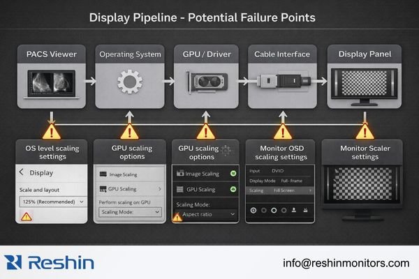
In practice, the most frequent failures are the least obvious because each layer tries to maintain usability or compatibility. Operating systems may apply desktop scaling for high-DPI environments. Graphics drivers may enable scaling to fill the screen or to accommodate non-preferred timing. Monitors may activate internal scalers when the input timing differs from what they expect, or when specific OSD “fit” modes are enabled. The key is to validate the same signal path and workflow used clinically.
Operating System and Application Issues
Desktop scaling settings, browser zoom levels, and remote desktop resizing/compression can all introduce resampling before the image ever reaches the panel. Some applications may also apply their own scaling even when set to “100%,” particularly in high-DPI contexts. For verification, reduce ambiguity by testing with OS scaling set to 100% and using a test pattern displayed in a way that avoids additional application-level resizing.
Graphics Driver Configuration
GPU scaling options3, output timing mismatches, and driver “helpful” defaults can force resampling at the driver level. Even at native resolution, the graphics system may still scale if the output timing/refresh is non-standard or if “overscan/underscan” adjustments are in effect. For stable verification, aim for a standard, native output mode with GPU scaling disabled, and avoid any control-panel settings that resize the desktop to fit.
Monitor Processing
Internal monitor scalers can activate due to aspect ratio processing, overscan compensation, or “fit to screen” modes. Some monitors may scale even at native resolution if the input timing does not match their preferred specifications, or if a non-1:1 scaling mode is selected in the OSD. Always verify scaling behavior on the exact input port used clinically, since behavior can vary between inputs.
How to Verify 1:1 Pixel Mapping Step by Step?
Systematic verification requires testing the complete signal path from application to display with known test patterns.
Start by establishing a clean baseline: set OS display scaling to 100%, configure desktop resolution to match the monitor’s native resolution, and disable GPU scaling. Then use pixel-level test patterns to verify that single-pixel features appear crisp and stable without gray blending or shimmering.
A reliable workflow is to lock down the environment first, then confirm pixel behavior with patterns that make resampling unmistakable. The goal is a pass/fail outcome: either single-pixel features remain discrete, or they blend—indicating scaling somewhere in the chain.
Configuration Baseline Setup
First, establish a clean configuration baseline. Set the operating system display scaling to 100% and configure the desktop resolution to exactly match the monitor’s native pixel matrix4. Confirm the output refresh/timing is a standard mode the monitor accepts without resizing, since timing differences at the same resolution can still trigger processing. In the graphics control panel, disable GPU scaling or set it to “no scaling,” and avoid any overscan adjustments that might resize the active image area.
Monitor Configuration
In the monitor’s on-screen display menu, select 1:1, dot-by-dot, native, or no-scaling modes, and disable any aspect-fill or zoom behaviors. Confirm that the selected input port matches your clinical configuration, since scaling behavior can vary between different inputs on the same monitor. If your environment uses KVMs, extenders, or signal converters, verify that the final output timing reaching the monitor remains consistent with your baseline.
Test Pattern Verification
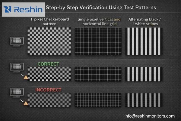
Use pixel-level test patterns to verify the complete pipeline. A 1-pixel checkerboard pattern should show crisp alternating pixels without any gray blending. Single-pixel vertical and horizontal lines should appear sharp and stable. Alternating black and white 1-pixel stripes should display clear boundaries without shimmering; if the pattern looks “soft,” shows gray mixing, or appears unstable when the image is static, resampling is still occurring somewhere in the path.
Clinical Application Testing
Finally, repeat the verification inside your actual PACS viewer at "100%" zoom using the same window and level settings that clinicians use in practice. Some viewers can apply their own scaling even when the desktop configuration is correct, so this step confirms that the complete clinical workflow maintains 1:1 pixel mapping. Contact us at info@reshinmonitors.com if you need assistance developing verification protocols for your specific PACS environment and monitor configuration.
How to Keep 1:1 Pixel Mapping Stable Over Time in Clinical QA?
Maintaining reliable 1:1 pixel mapping requires treating it as a controlled configuration item with regular verification.
Treat 1:1 pixel mapping as a configuration-controlled QA item by standardizing OS scaling, GPU driver versions, and output modes per monitor model. Include pixel-pattern spot checks in acceptance testing, after system updates, and whenever remote access tools are introduced, since these changes commonly re-enable scaling.
![]()
From a QA and engineering standpoint, the most effective protection against configuration drift is to define a known-good baseline and treat changes as triggers for re-verification. Pixel mapping issues often reappear after updates because defaults get reset, drivers change behavior, or new tools introduce resizing in the path.
Configuration Control Process
Document the complete configuration baseline including desktop resolution, refresh rate/timing5, GPU scaling state, and monitor OSD scaling mode for each workstation type. Include the specific input port used, since some monitors behave differently on different inputs even at the same resolution. This documentation is essential for troubleshooting “softness” reports and for restoring consistent behavior after maintenance.
Scheduled Verification Points
Include quick pixel-pattern verification in acceptance testing for new installations, after graphics driver or operating system updates, after graphics card replacement, and whenever remote access tools are introduced to the environment. Also consider re-checking after changes to KVMs, extenders, or workstation imaging policies, since these can unexpectedly re-enable scaling or alter timing.
Operational Integration
Ensure that clinical staff understand when they are viewing images at native pixels versus resampled views. Reading protocols should specify when 1:1 mapping is required, particularly for detailed review, measurement tasks, or specific modalities where pixel-level accuracy is critical for interpretation.
By combining configuration baselines with periodic verification, you reduce variability across reading rooms and over time, which is essential for consistent interpretation confidence and for troubleshooting when users report unexpected image quality changes.
Selecting Diagnostic Monitors That Support Reliable 1:1 Pixel Mapping
Monitor selection should prioritize native resolution alignment with clinical workflows and reliable scaling control features.
For reliable 1:1 pixel mapping, selection should start by matching clinical use cases to native resolution and typical viewing geometry. Choose a panel whose native pixel matrix aligns with your diagnostic workload so that native viewing is practical rather than constantly requiring scaling adjustments.
| Clinical Role / Application | Usage Pattern | Display Requirements | Recommended Model | Key Integration Considerations |
|---|---|---|---|---|
| General Radiology Reading | Multi-modality interpretation | 3MP-5MP native resolution, stable 1:1 modes | MD33G | Native timing support, reliable dot-by-dot mode |
| Mammography Screening | High-resolution detail work | 5MP native resolution, precise pixel mapping | MD52G | Exact pixel correspondence, stable calibration |
| Clinical Review Workstation | Secondary reading, consultation | 3MP resolution, consistent scaling behavior | MD32C | Predictable 1:1 operation, easy verification |
| Multi-Modality Diagnostic | Mixed workflow support | Large format, flexible scaling options | MD120C | Multiple native modes, reliable pixel mapping |
| Portable Diagnostic Review | Mobile applications, multiple sites | Compact design, consistent pixel behavior | MD26C | Stable 1:1 mapping, portable reliability |
Next, evaluate the signal chain compatibility by ensuring your workstations can output native timing over the intended interfaces, and confirm that the monitor provides a true no-scaling mode on those inputs with predictable behavior across power cycles and input changes.
Because diagnostic workflows depend on consistency, prioritize displays that support ongoing calibration and QA procedures. Pixel mapping verification is most reliable when the broader display pipeline remains stable—native timing, no scaling, and calibrated response should remain repeatable after maintenance and software updates.
Consider serviceability and lifecycle management as part of the selection process. Standardized deployment profiles, documented OSD and GPU settings, and manageable replacement strategies help ensure that monitor swaps don’t silently change scaling behavior and compromise reading consistency across workstations.
FAQ
If my PACS viewer says "100%," is that always 1:1 pixel mapping?
Not always. "100%" may refer to the viewer’s internal zoom level, while the OS, GPU, or monitor can still be scaling the final output, so you must confirm native timing and no-scaling settings end-to-end with a pixel test pattern.
What is the quickest visual sign that scaling is happening?
Single-pixel patterns look "gray" or slightly blurred instead of crisp black/white, and fine alternating stripes may shimmer or show uneven moiré when the image is static—both are common signs of resampling.
Does OS display scaling automatically break 1:1?
It often does for desktop-rendered content because the OS scales UI elements, but 1:1 for image pixels can still be achieved inside some viewers if they bypass desktop scaling; the safe approach for verification is setting OS scaling to 100% during testing.
Can the monitor itself force scaling even at native resolution?
Yes. Some OSD modes apply "fill" or aspect processing, and certain inputs can trigger internal scalers; you should explicitly select a dot-by-dot/native/no-scaling mode and confirm behavior on the exact input you use clinically.
Does verifying 1:1 replace DICOM calibration or routine QC?
No. Pixel mapping ensures geometric fidelity at the pixel level, while DICOM calibration and QC ensure luminance response, grayscale consistency, and stability over time; they address different failure modes and should be used together.
Why does remote desktop often ruin 1:1 verification?
Remote tools frequently rescale frames to fit bandwidth and client display size, introduce compression, and alter color sampling; for verification and diagnostic reading, use a local, direct connection whenever possible.
Conclusion
Verifying 1:1 pixel mapping requires systematic testing of the complete display pipeline from PACS viewer to monitor panel, since hidden scaling can occur at multiple points without obvious visual indication. The verification process must cover operating system scaling settings, graphics driver configuration, interface timing, and monitor scaling modes to ensure that diagnostic images are displayed with true pixel correspondence.
At Reshin, we design diagnostic monitors with reliable dot-by-dot display modes and provide clear documentation for maintaining 1:1 pixel mapping throughout the display lifecycle. Our engineering team works with clinical teams to develop verification protocols that integrate with existing QA procedures, ensuring that pixel-level accuracy remains consistent across workstations and over time. When combined with proper calibration and routine quality control, verified 1:1 pixel mapping provides the foundation for confident diagnostic interpretation.
✉️ info@reshinmonitors.com
🌐 https://reshinmonitors.com/
-
Exploring methods for achieving 1:1 pixel mapping can enhance your display’s clarity and performance. ↩
-
Exploring the role of diagnostic reading can enhance your knowledge of medical imaging and its implications for patient care. ↩
-
Understanding GPU scaling options is crucial for optimizing image quality and avoiding unwanted resampling. ↩
-
Understanding the native pixel matrix is crucial for achieving optimal display quality and performance. ↩
-
Exploring refresh rate impacts can help ensure optimal performance and reduce image quality issues. ↩