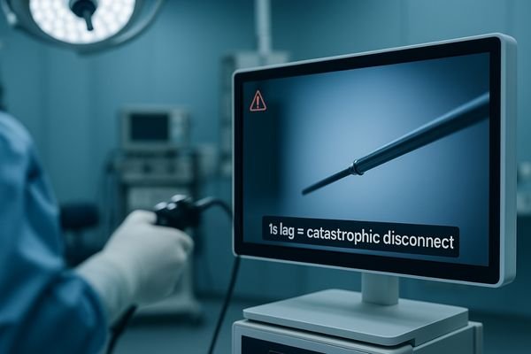
During a delicate procedure, a surgeon’s hands move with precision, but the image on the screen does not keep up. A one-second delay completely disrupts hand-eye coordination, turning a routine action into a high-risk maneuver.
A one-second lag in a surgical display creates a catastrophic disconnect between action and perception, leading to instrument overshoot, tissue damage, and increased complication rates. True real-time performance is a non-negotiable safety requirement.
In the operating room, the term "real-time" is not a marketing buzzword; it is a fundamental requirement for patient safety. Surgeons rely on a seamless visual feedback loop where their hand movements are instantly and accurately reflected on the surgical display. Even a delay that seems imperceptible in other contexts can be devastating during surgery. A one-second lag is an extreme case, but it powerfully illustrates the danger of latency—the delay between an event happening and it being seen. This delay is not a single, simple problem but a cumulative effect of every component in the video chain, from the endoscope’s camera to the display panel itself. Understanding, measuring, and mitigating this latency is one of the most critical challenges in designing modern integrated operating rooms. This article explores the causes and catastrophic clinical risks of display latency1 and outlines a systematic approach to engineering a verifiable, low-latency video ecosystem.
Defining and measuring surgical display latency
To control latency, treat it as an end-to-end phenomenon and measure for both typical and worst-case scenarios across real surgical tasks.
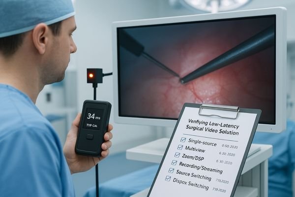
Surgical display latency is the total “glass-to-glass” delay from camera to screen. It must be measured end-to-end, logging typical and worst-case values, including added lag during dynamic events like source switching.
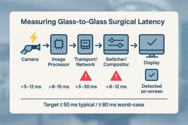
Surgical display latency2 is the total time it takes for an image to travel from the "glass" of the endoscope or surgical camera lens to the "glass" of the monitor screen. It is a cumulative delay, with milliseconds being added at every step of the video signal chain. Simply looking at the specification sheet for a single component, like the display’s response time, is misleading. A comprehensive measurement must capture the entire journey. This involves specialized equipment that can generate a light signal at the camera source and measure the precise moment it appears on the display.
What to Measure
Track both typical and worst-case latency, because delay is not constant. Capture spikes during common intraoperative events, including:
- Switching video sources (e.g., endoscope ↔ PACS)
- Enabling PIP/PBP or other multiview layouts
- Zooming or applying DSP
- Starting recording/streaming
Set clear targets and verify under all conditions: glass-to-glass ≤ 50 ms (typical) / ≤ 80 ms (worst-case). Log results in an audit-ready record.
Technical causes of OR video delay
Latency is “death by a thousand cuts”—small delays from many places that add up unless the chain is engineered for determinism.
Common latency drivers include image processing like scaling, signal conversions, network buffering or retransmissions, under-specified hardware, and complex multiview processing stacks without a locked signal policy.
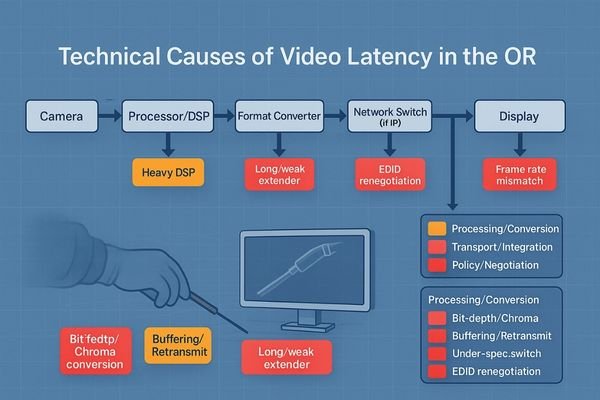
Understanding the technical root causes of video delay is essential for designing a low-latency system3. Delay accumulates across the chain, and identifying these sources is the first step toward mitigation. One weak link—display, signal, or environment—breaks the chain.
Processing and Conversion Delays
Non-native scaling and resampling add processing time. Heavy DSP (denoise/sharpen/stabilize) further increases latency. Any conversions (e.g., 8-bit → 10-bit, 4:2:2 ↔ 4:4:4) or frame–refresh mismatches can introduce judder, dropped/repeated frames, and perceived lag.
Transport and Integration Bottlenecks
Video-over-IP/KVM can add variable latency via buffering and retransmits. In wired systems, under-spec switchers, long/weak extenders, or daisy-chained gear degrade signal integrity. Deep multiview compositing stacks add cumulative processing. Unlocked EDID/bit-depth forces renegotiation and mode switches.
Clinical risks of display latency
When the visual loop is delayed, fine motor control and team timing degrade—risk rises even if no single error is “dramatic.”
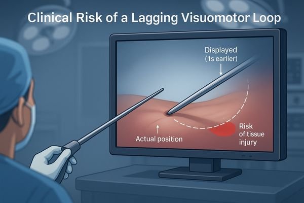
A lengthened visuomotor loop caused by latency drives instrument overshoot, uneven sutures, and thermal injury from excessive dwell time. This increases complication risks, case duration, and the surgical team’s cognitive load.
Impaired Motor Control4 and Tissue Damage
Instrument overshoot can cause unintended dissections or punctures. Suturing precision suffers, yielding uneven or insecure stitches. With energy devices, dwell time increases as the surgeon waits for visual confirmation, risking thermal injury.
Increased Cognitive Load and Procedural Time
Persistent compensation for lag exhausts attention and increases late-procedure error propensity. Unpredictable delay during switching/zoom desynchronizes cues among team members, fueling miscommunication. Net effect: higher complication risk and longer cases.
A verifiable low-latency solution
Low latency is engineered—not hoped for—by locking transport, signal policy, layouts, and QA into a single deterministic system.
Engineer determinism with high-bandwidth transport, lock the signal chain to 10-bit 4:4:4 with fixed EDID, use fixed multiview templates, and institutionalize glass-to-glass latency testing with audit logs.
Building a Deterministic Pipeline
Use point-to-point, high-bandwidth links: DisplayPort for near-field, 12G-SDI or fiber SDI for distance. Enforce end-to-end 10-bit, 4:4:45 and fixed EDID/bit-depth policies; disable non-essential DSP. Align frame output and display refresh (use genlock if needed). For multiview, avoid ad hoc windows—enforce fixed templates (e.g., Quad-OR-A, PIP-Scope-L, PBP-Scope-Vitals) bound to user profiles.
Room environment: maintain 20–40 lux ambient light with bias lighting; eliminate direct glare and reflections to preserve near-black visibility.
The Role of Institutionalized Testing
Make testing routine: perform glass-to-glass measurements at install and on a periodic schedule, covering single-source, multiview, zoom/DSP, recording/streaming, and source switching. Target ≤ 50 ms typical / ≤ 80 ms worst-case and capture results in auditable logs.
Latency Test Matrix (example template)
| Scenario | Typical (ms) | Worst-case (ms) | Pass/Fail | Notes |
|---|---|---|---|---|
| Single source (native) | ||||
| Multiview (Quad template) | ||||
| Zoom / DSP active | ||||
| Recording/Streaming ON | ||||
| Source switch (A→B) |
Recommended Low-Latency Surgical Displays
| Model | Size/Resolution | 10-bit | 4:4:4 | 12G-SDI | DP/HDMI | Fixed Multiview | EDID Lock | Notes |
|---|---|---|---|---|---|---|---|---|
| MS321PB | 31.5" 4K | Yes | Yes | Yes | Yes | Yes | Yes | Tower/boom primary display |
| MS322PB | 32" 4K | Yes | Yes | Yes | Yes | Yes | Yes | Same class, size preference |
| MS550P | 55" 4K | Yes | Yes | — | Yes | Yes | Yes | Wall/main team display |
| MS270P | 27" FHD | Yes | Yes | — | Yes | Yes | Yes | Mobile cart / auxiliary |
| MS220SA | 21.5" FHD | Yes | Yes | — | Yes | Template-ready | Yes | Basic endoscopy/info |
For specs or demo images: info@reshinmonitors.com
Measurable business value
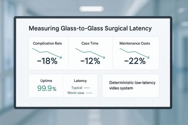
Low-latency, fixed-template systems reduce risk and improve throughput—benefits that are measurable in clinical and operational KPIs.
Low latency reduces errors and shortens case times, while standardized and auditable systems cut rework, simplify maintenance, and lower the total cost of ownership, making deployments more predictable.
Operational and Financial Gains
Standardizing a deterministic video chain with a consistent BOM and cabling plan simplifies installation, maintenance, and troubleshooting. Audit-ready latency reports streamline acceptance and compliance. Over time, reliability lowers TCO by reducing support overhead and making upgrades predictable.
FAQ
Does a one-second lag always mean there is a network problem?
No. Significant latency can accumulate in wired systems via scaling, heavy DSP, frame-rate mismatches, and cascaded extenders/switchers.
Action: profile each hop; log per-scenario latency into the matrix.
Is using multiview (PIP/PBP) inherently slower?
It depends on implementation. Software compositing can add variable delay; hardware compositors with fixed templates and sufficient bandwidth can make it negligible.
Action: test with your target layout active and record typical/worst-case.
What is an acceptable latency threshold in surgery?
Define it per clinical scenario and institutionalize in SOPs.
Action: run glass-to-glass tests for laparoscopy/arthroscopy, etc., and set ≤ 50 ms typical / ≤ 80 ms worst-case targets with logs.
Can wireless video work in the OR?
Only within a strict latency budget and with a wired fallback.
Action: verify stability under peak-load conditions; document failover behavior and thresholds.
Conclusion
Make "real-time" a measurable, repeatable, and auditable standard through deterministic transport, locked signal chains, fixed templates, and routine QA—then verify it with glass-to-glass ≤ 50 ms typical / ≤ 80 ms worst-case across real OR scenarios. Actual thresholds should align with your clinical SOPs and regulatory guidance. ⚙️
👉 For expert consultation and Reshin’s real-time surgical display solutions, contact info@reshinmonitors.com.
-
Exploring display latency can reveal its impact on surgical precision and patient care, making it essential for medical professionals. ↩
-
Understanding surgical display latency is crucial for optimizing surgical procedures and ensuring real-time image accuracy. ↩
-
Exploring low-latency system design can significantly enhance user experience in real-time video applications. ↩
-
Understanding the impact of impaired motor control can enhance surgical techniques and patient safety. ↩
-
Understanding 10-bit, 4:4:4 is crucial for high-quality video production. Explore this link to learn its benefits and applications. ↩