In OEM medical display projects, many of the most expensive delays do not begin in validation or production. They begin much earlier, when the project starts with incomplete inputs, unclear boundaries, or assumptions that have not been verified across the full system.
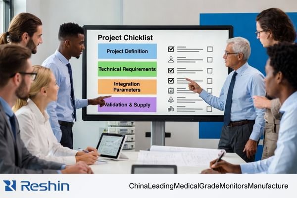
A practical OEM medical display project checklist should be established before RFQ, sampling, or deep customization begins. At a minimum, teams should lock the project type, system role, real use scenario, target market, performance baseline, signal-chain conditions, mechanical constraints, validation ownership, and supply continuity assumptions.
When these items are defined early, quotations become more accurate, samples become more meaningful, and later stages such as specification freeze, pilot builds, and volume production become easier to manage. This is also why early alignment matters when working with a medical display manufacturer: the quality of the project input often determines the quality of the project outcome.
A common problem in early-stage discussions is that the request is too narrow to support a reliable project decision. A statement such as “24-inch medical display” or “4K surgical monitor” may describe part of the requirement, but it does not define the system role, the signal path, the integration method, the validation target, or the expected supply model. Before a project truly starts, those inputs need to be made explicit.
Quick OEM Medical Display Startup Checklist
| Checklist Item | What Should Be Confirmed Before the Project Starts | Why It Matters |
|---|---|---|
| Project Type | New platform, upgrade, EOL replacement, or continuation project | Defines technical scope, timing, and risk level |
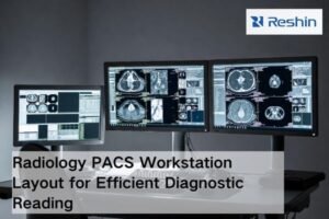
| System Role | Diagnostic viewing, clinical review, surgical visualization, equipment UI, or secondary display | Determines image priorities, reliability needs, and validation direction |
| Use Scenario | OR, reading room, cart, bedside device, consultation room, or embedded equipment | Affects brightness strategy, surface treatment, durability, and cleaning design |
| Target Market | Domestic, export, or multi-country rollout | Impacts documentation, labeling, registration coordination, and delivery planning |
| Performance Baseline1 | Size, resolution, luminance, contrast, color or grayscale priorities | Prevents spec drift and keeps technical evaluation focused |
| Signal Chain | Source output, interface type, mid-chain devices, switching logic, real operating mode | Reduces compatibility failures, EDID issues, and scaling surprises |
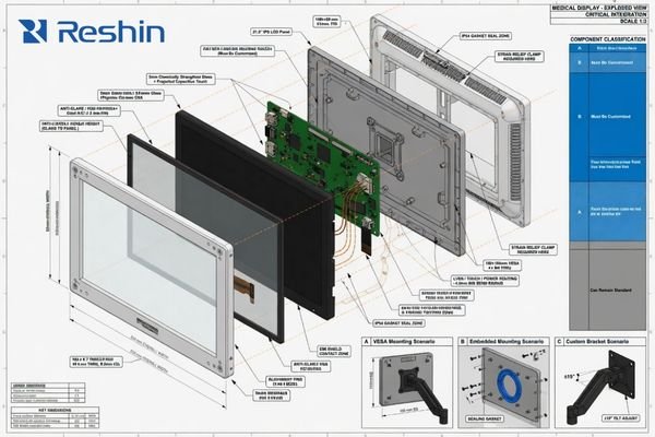
| Mechanical Integration | Outer dimensions, cutout, mounting, front surface, enclosure constraints | Prevents redesign caused by late structural conflicts |
| Customization Boundary | What must be custom versus what should stay standard | Controls cost, complexity, lead time, and repeatability |
| Validation Ownership | Sample purpose, acceptance criteria, who signs off, and failure handling path | Makes sample review objective rather than subjective |
| Supply Continuity | Spec freeze timing, revision rules, material continuity, and change notification | Supports a more stable transition to pilot and volume supply |
Confirm the Project Type and the Display’s Role in the System
The first requirement is to define what kind of project is actually being launched. A new platform development project is different from an upgrade to an existing system, and both are different from a direct replacement for an end-of-life component. These are not administrative labels. They change the technical scope, the time pressure, the validation burden, and the amount of customization that is realistic.
Before any detailed specification discussion, the project needs a clear identity: new development, platform upgrade, legacy replacement, or continuation of an existing build. That definition determines how much of the design can remain standard and how much must be reviewed as a new engineering task.
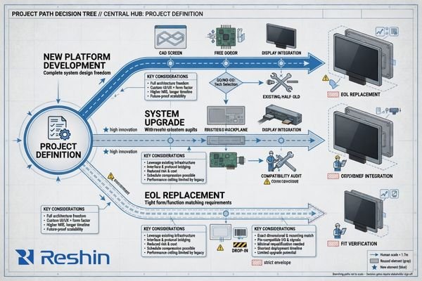
Define the Project Path
A project that starts as a new platform usually has broader flexibility but also carries more engineering uncertainty. An upgrade program often has tighter compatibility limits because part of the system architecture already exists. An EOL replacement project usually places the strongest pressure on form factor, interface behavior, timing, and supply continuity because the display must fit into a system that is already in use or already committed to downstream customers.
The project path should therefore be made explicit at the beginning, not inferred later from scattered requirements.
Clarify the Display’s Functional Role
The display’s role inside the complete medical system also needs to be fixed at this stage. A display used for surgical visualization2 has different priorities from one used as a machine interface, a consultation display, or a secondary information screen. Once the system role is clear, the performance target, interface review, and validation logic become much easier to define.
A practical project kickoff usually begins by confirming the following points:
- Whether the project is a new platform, an upgrade, or a replacement
- Whether the display is primary, secondary, or interface-oriented in the final system
- Whether the near-term objective is RFQ, engineering sample review, registration preparation, pilot build, or production launch
- Whether the project requires a standard model, light modification, or deeper customization
Without this boundary, teams often start discussing panel specifications too early, while the actual project assumptions remain unstable.
Confirm the Real Use Scenario and the Target Market
A medical display cannot be evaluated correctly without understanding where and how it will actually be used. The same display size and resolution may perform well in one environment and fail in another because the real operating conditions are different.
The actual use scenario includes the physical environment, the usage pattern, the primary operator, and the operational constraints around light, cleaning, movement, and system integration. The target market adds another layer because documentation, labeling, and regulatory coordination are rarely identical across projects.

Map the Real Operating Environment
The environmental context should be defined in concrete terms:
- Operating room, reading room, bedside device, consultation room, mobile cart, or embedded enclosure
- Continuous operation or intermittent use
- Fixed installation or mobile workflow
- High ambient light, controlled lighting, or mixed-light conditions
- Routine cleaning, frequent disinfection, or special surface handling requirements3
- Primary users such as physicians, technicians, nurses, or equipment operators
A display chosen for a bright OR with frequent wipe-down cycles may need a very different front-surface strategy from one used in a darker imaging workstation. The use environment changes how brightness, reflection control, durability, and accessibility should be evaluated.
Align the Target Market and Documentation Path
The target market should also be locked early, especially when the project is intended for export or multi-country supply. That decision influences document planning, project timing, labeling language, registration coordination, and the expected level of technical documentation. If a project requires structured compliance support, that expectation should be aligned before the sample phase rather than after it.
A useful way to reduce ambiguity at this stage is to separate the startup input into two sides:
| Buyer Should Prepare | Supplier Should Clarify |
|---|---|
| System role in the final device | Feasibility boundary of the proposed solution |
| Intended use environment and user group | Which requirements can stay standard and which need customization |
| Target countries or markets | Documentation scope and project assumptions |
| Cleaning, surface, and environmental constraints | Validation approach and sample objectives |
| Project timeline and stage target | Risks that may affect lead time, compatibility, or repeatability |
When this information is defined early, the project moves forward on a more realistic foundation.
Lock the Core Display Performance and Image Requirements
Once the project role and environment are clear, the next step is to translate them into a usable display performance baseline. The goal here is not to chase the highest possible numbers. The goal is to define the image performance the system actually needs and the limits that must be protected during evaluation and production.
A useful performance baseline typically includes size, resolution, luminance, contrast, viewing behavior, and whether the priority is color reproduction or grayscale performance. It should also identify any workflow-specific functions that affect controller selection or firmware behavior.

In project reviews, the most stable decisions come from defining not only the target specification, but also the acceptable lower limit. That makes sample evaluation more objective and reduces the tendency for the requirement to drift after the first engineering discussion.
The following baseline categories usually need to be confirmed:
| Performance Category | What Should Be Locked | Why It Matters |
|---|---|---|
| Core Metrics4 | Size, resolution, luminance, contrast ratio | Establishes the basic technical target |
| Image Priority | Color-focused, grayscale-focused, or mixed-use | Aligns panel choice, calibration focus, and validation emphasis |
| Viewing Requirements | Viewing angle, image consistency, stability over time | Affects reliability in real clinical use |
| Workflow Functions | PiP/PbP, image rotation, fixed aspect ratio, preset modes | Defines controller and firmware requirements |
| Operational Stability | Luminance consistency, drift tolerance, repeatable image behavior | Supports long-term usability and predictable acceptance |
It is also important to describe image needs in system language rather than in isolated display language. Some projects prioritize color separation under procedure lighting. Others prioritize grayscale readability, fixed image mapping, or stable long-duration viewing. The more directly those needs are stated, the easier it becomes to build a meaningful validation plan.
Confirm the Interface Configuration and the Full Signal-Chain Conditions
Interface review should never stop at the connector name. In real OEM medical systems, the display is rarely connected in a simple point-to-point way. What matters is the actual signal path that will exist in the finished system.
The signal-chain review should confirm the source device, the output parameters, any mid-chain hardware, the switching logic, and the final display state in actual use. Compatibility problems often come from the full chain rather than from the display input alone.
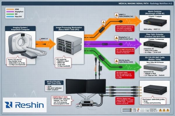
A reliable interface review usually requires more than a list of requested inputs. It needs the project team to describe how the signal is generated, processed, routed, and presented in the real product. That includes questions such as:
- What is the source device and its native output mode?
- What resolution, refresh rate, and color format are expected in actual operation?
- Are there capture cards, processor boards, switchers, routers, converters, or extenders in the path?
- Is there multi-source switching, automatic input selection, or preset priority logic?
- Does the system depend on a fixed EDID behavior or a specific scaling outcome?
- What is the expected display mode in the final device, not just in a lab setup?
Many integration delays are caused by issues that only appear once the real signal chain5 is in place: handshaking instability, unexpected downscaling, blank-screen events, timing mismatches, or latency introduced by mid-chain devices. This is why early signal-chain confirmation is more useful than simply asking whether a display “has HDMI” or “supports 4K.”
Define the Mechanical Integration Conditions and the Customization Boundary
Electrical compatibility is only one part of a successful OEM display project. The display must also fit the system mechanically, function correctly in the enclosure, and remain practical to manufacture and support.
Mechanical integration should define dimensional limits, cutout or embedded installation conditions, mounting method, front-surface structure, and operational constraints around cleaning and physical access. In parallel, the customization boundary should separate what must be changed from what should remain standardized.
Confirm Mechanical Constraints Before Customization
At this stage, the project should confirm:
- Outer dimension limits and bezel constraints
- Cutout dimensions for embedded integration, if applicable
- Mounting method such as VESA, arm, cart, wall, or enclosure integration
- Front-panel design, protective glass, optical bonding, anti-reflection surface, or easy-clean requirements
- Button placement, OSD logic, default startup state, and interface access
- Logo, label, cable, packaging, and accessory requirements
These conditions determine whether a concept can be integrated smoothly or whether later redesign is likely. Mechanical uncertainty often creates more project delay than teams expect, especially when enclosure space, mounting points, and surface requirements are not fixed early.
Separate Required Customization from Standard Elements
This is also the point where the project should define the real scope of display customization. In practice, the most stable OEM programs are not the ones that customize everything. They are the ones that distinguish clearly between mandatory customization and areas where standardization improves lead time, cost control, repeatability, and future support.
A simple distinction can help keep the project realistic:
| Must Be Customized | Can Often Remain Standard |
|---|---|
| Critical front-panel structure | Internal platform elements that do not affect the final use case |
| Required mounting or enclosure interface | Standard controller architecture where no workflow conflict exists |
| Application-specific OSD behavior | Common packaging items with no project-specific need |
| Mandatory labeling or user-facing design items | Proven components that already meet project needs |
When this boundary is defined early, the project is easier to quote, easier to validate, and easier to transition into repeatable supply.
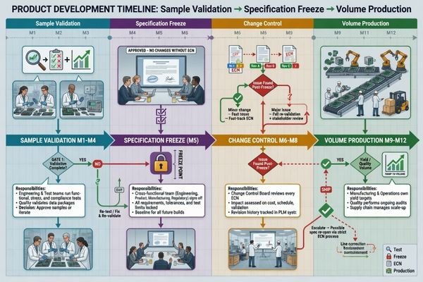
Lock the Validation Plan, Change Mechanism, and Supply Continuity Before the Project Starts
A project is not truly ready to start until the team agrees on what the sample is for, how success will be judged, and how later changes will be handled. This is especially important in medical device programs, where a good-looking sample alone is not enough to support a stable long-term project.
Before kickoff, the project should define the purpose of each sample phase, the acceptance criteria, the approval owner, the specification-freeze point, and the rules around future component or specification changes. These decisions directly affect project stability from RFQ through volume production.
Define the Validation Scope and Acceptance Criteria
The validation plan should answer clear operational questions:
- Is the sample intended for appearance review, interface confirmation, functional testing, customer evaluation, or environmental assessment?
- Which items must be validated: brightness consistency, grayscale or color behavior, signal compatibility, long-duration operation, cleaning durability, or structural reliability?
- Who decides whether the result passes?
- What happens if a test does not pass: revision, alternative proposal, scope reduction, or requirement reset?
Without clear acceptance ownership, sample review often becomes subjective. A technically acceptable sample may still be delayed if the project team has not agreed on what counts as pass, what counts as rework, and what should trigger a broader requirement review.
Align Change Control and Supply Continuity Early
Change control and supply continuity6 also need to be addressed at the project start, even if they will become more important later. The team should at least align on:
- When the working specification will be frozen
- How revisions will be identified and communicated
- Which key materials or components may affect continuity
- How substitutions will be reviewed
- What level of batch-to-batch consistency is expected once the project moves beyond sampling
A useful way to structure this is by project stage:
| Stage | What Should Already Be Clear |
|---|---|
| Before RFQ | System role, target market, basic performance baseline, signal source, mechanical limits |
| Before Sample | Sample purpose, key validation items, interface assumptions, customization boundary |
| Before Spec Freeze | Acceptance criteria, approval ownership, revision logic, continuity assumptions |
| Before Pilot / Volume | Repeatable build scope, controlled release conditions, communication path for changes |
This stage-based view keeps the article focused on startup decisions rather than turning it into a full lifecycle governance guide.
Conclusion
An OEM medical display project becomes more manageable when the project inputs are defined before technical work begins in earnest. The most important startup decisions are usually not about a single specification. They are about whether the system role, use environment, performance baseline, signal path, mechanical constraints, validation ownership, and supply assumptions have been made clear enough to support a stable project path.
For buyers, product teams, and engineering teams, a strong checklist does not add unnecessary process. It reduces avoidable rework. When the right questions are answered early, RFQ becomes more accurate, samples become more useful, and later stages such as specification freeze and volume supply become easier to control.
If you are preparing a new project and want to align the technical scope earlier, start by reviewing your system requirements with a qualified medical display manufacturer and define where display customization or structured compliance support may actually be needed.
-
Understanding performance baselines is crucial for maintaining project focus and preventing specification drift. ↩
-
Exploring the requirements for surgical visualization displays can enhance your knowledge of medical technology and improve project outcomes. ↩
-
Exploring surface handling requirements ensures your product maintains hygiene and safety standards in critical settings. ↩
-
Understanding core metrics is crucial for establishing technical targets in project evaluations. ↩
-
Understanding the signal chain is crucial for troubleshooting and optimizing performance in audio and video systems. ↩
-
Ensuring supply continuity is vital for project success; learn strategies to avoid disruptions. ↩