Endoscopy display validation becomes difficult when the monitor is tested alone. I usually start from the full video chain because camera processor output, routing equipment, cable path, input recognition, and display settings can all affect visual behavior.
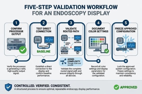
Endoscopy display validation should confirm the complete video chain from camera head and processor to signal routing, display input, color output settings, and user-side viewing expectations. A practical validation workflow should follow five steps: confirm the camera processor output, test direct display connection, validate the routed signal path, document color output settings, and freeze the approved configuration for batch integration.
In endoscopy projects, the monitor is the final viewing point, but it is not the only source of display risk. The camera processor may output different formats, the signal may pass through a router or recorder, and the display may respond differently depending on input recognition, scaling behavior, color settings, and signal switching. These conditions should be reviewed before model approval.
That is why I connect validation with the real system chain used by endoscopy system manufacturers. I do not treat resolution, size, or panel type as the starting point. I first check the camera processor, output format, routing path, target screen size, installation plan, and acceptance criteria. For endoscopy monitor validation, the goal is not only to make the image appear on screen. The goal is to confirm whether the display can behave consistently in the intended camera processor and OR signal chain.
Why Endoscopy Display Validation Should Start from the Full Video Chain
Endoscopy display validation should not begin with display resolution alone. The complete video path should be understood before sample approval, especially when routing equipment, recorder pass-through, or OR integration systems are involved.
The full video chain includes camera head, camera processor, output format, routing equipment, cable path, display input, image settings, and user-side viewing expectations. If any part is not confirmed, the display sample may pass a simple bench test but fail system-chain validation.
When I review an endoscopy display project, I separate the monitor specification from the system behavior. A display may support the expected resolution, but the camera processor, cable length, routing device, input negotiation, or power-on sequence may still create unstable signal behavior or unexpected image presentation.
The Camera Processor Defines the First Validation Condition
The camera processor output should be confirmed before the display sample is approved. I review the output interface, resolution, refresh rate, output mode, signal format, and output preset. If the processor output is not clearly defined, the display test may not represent the final system. This matters for both FHD and 4K projects because the approved configuration should be repeatable during batch integration.
Routing Equipment Can Change Display Behavior
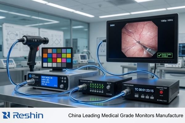
Many projects do not connect the camera processor directly to the display. The signal may pass through a router, recorder, capture device, switcher, or OR integration system. For surgical systems and OR integrators, this routed path should be tested because input recognition, scaling behavior, cable stability, source switching, and signal fallback may differ from direct connection.
What to Confirm Between the Camera Processor and Display Input
The connection between camera processor and display input should be reviewed before sample approval. I treat this step as a technical gate for surgical monitor signal compatibility, signal stability, and repeatable visual behavior.
Before approving an endoscopy display sample, the project team should confirm output interface, resolution, refresh rate, color space or output mode, signal format, cable type, cable length, routing device, EDID or input recognition behavior, scaling behavior, latency sensitivity, fallback input options, and source switching conditions.

The first group of checks covers signal compatibility. I confirm whether the processor output is HDMI, SDI, DisplayPort, DVI, or another interface depending on project requirements. I also check the expected resolution, refresh rate, signal format, cable type, cable length, and input recognition behavior. If routing equipment is used, the routed signal path should be tested instead of assuming it behaves the same as direct output. EDID or input negotiation should also be reviewed because a display may accept one signal mode but scale another mode unexpectedly.
The second group of checks covers workflow fit. Scaling behavior, latency sensitivity, backup input options, color output behavior, source switching, and user-side viewing expectations should be confirmed under agreed test conditions. In Reshin endoscopy display discussions, I usually ask the project team to share the camera processor model, output format, routing path, cable length, target screen size, installation quantity, and validation schedule before recommending a display direction. This helps connect the surgical monitor sample to the real integration environment instead of a simplified bench test.
Endoscopy Display Validation Matrix for Camera Processor, Signal Routing and Color Output
A validation matrix helps the project team review the full system chain in a controlled way. I use it to separate possible risk from safer approval action before sample testing moves toward batch integration.
An endoscopy display validation matrix should cover camera processor output, direct connection, routed signal path, EDID or input negotiation, 4K chain, legacy HD or FHD output, color output behavior, latency sensitivity, source switching, multi-room deployment, connector variation, and recorder pass-through.
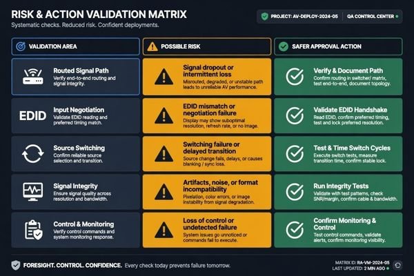
The table below is a practical validation framework. It is not a universal acceptance standard. The project team should adjust each item according to the camera processor, signal architecture, procedure workflow, installation environment, and batch integration plan.
| Validation Area | Possible Risk | What to Test | Safer Approval Action |
|---|---|---|---|
| Camera processor output | Display may not recognize the intended signal format | Output interface, resolution, refresh rate, and output mode | Approve only the tested processor output configuration |
| Direct display connection | A simple connection may hide later routing problems1 | Processor-to-display signal stability and input behavior | Use direct testing as a baseline, not as the only approval condition |
| Routed signal path | Router or integration equipment may change signal behavior | Full path through router, switcher, recorder, or OR system | Validate the display through the actual routed path |
| EDID or input negotiation | Processor or routing device may select an unexpected signal mode | EDID behavior, input recognition, preferred resolution, and scaling | Freeze the approved input mode and avoid untested negotiation assumptions |
| 4K signal chain | Cable, routing, or output limitation may affect stability | 4K output, cable length, input recognition, and image display mode | Freeze approved cable and routing conditions before batch use |
| HD or FHD legacy processor output | Scaling or aspect ratio behavior may differ from expectation | Legacy output format, scaling, display mode, and image layout | Confirm acceptable visual behavior under the actual legacy output |
| Color output behavior | Visual differences may become subjective and hard to reproduce | Processor settings, white balance, display preset, brightness, and contrast | Use agreed test settings and document the approved configuration |
| Latency-sensitive procedures | Added routing or processing may affect workflow acceptance | Direct and routed signal response under representative use | Keep latency-sensitive approval tied to the tested system chain |
| Source switching or power-on sequence | Display behavior may change after input switching or system restart | Power-on order, source switching, reconnect behavior, and fallback input | Test the expected operating sequence before approving the configuration |
| Multi-room deployment | Different rooms may use different cables, routers, or processors | Room-by-room signal path, display input, and installation variation | Standardize approved configurations by room group |
| Cable or connector variation | Field cables may create unstable input recognition | Cable type, connector quality, length, and routing stress | Define approved cable types and installation limits |
| Capture or recorder pass-through | Pass-through devices may alter recognition or output format | Processor to recorder to display behavior | Approve the display only after pass-through validation when used |
This matrix helps prevent a sample from being approved under one simplified condition and then failing during integration. At Reshin, I usually use this type of validation matrix before recommending a surgical monitor sample. I separate direct processor output, routed OR integration paths, 4K signal chains, legacy FHD outputs, multi-room deployment groups, and recorder pass-through conditions so the customer can approve one repeatable configuration instead of relying on a single bench test.
I also prefer to record the processor model, signal path, cable configuration, display settings, input mode, source switching behavior, and acceptance result before the project moves toward batch deployment. This makes the approved configuration easier to repeat during production, installation, service communication, and future replacement.
How to Validate Color Output Without Turning It into a Subjective Preference Test
Color output validation can become unclear if every reviewer adjusts settings by preference. I prefer controlled, repeatable conditions so the result can be reproduced during endoscopy monitor sample testing and batch integration.
Color output validation should compare camera processor settings, white balance routine, display presets, brightness and contrast settings, color temperature, live camera feed, test pattern behavior, and user acceptance under agreed conditions. The goal is stable and acceptable visual output, not a universal claim of perfect color.
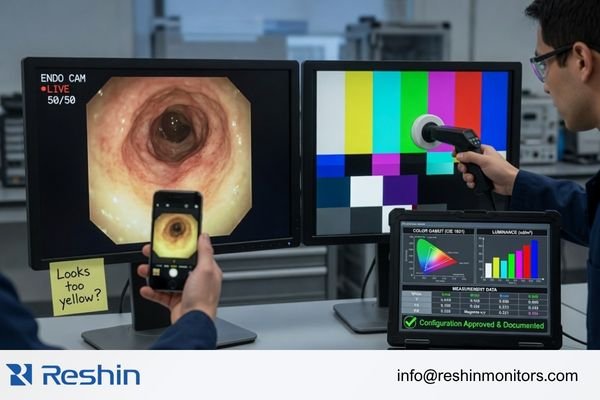
I start by freezing the camera processor settings used for the test. The white balance routine, output mode, brightness and contrast settings, display preset, and color temperature should be recorded. A live camera feed and test pattern can both be useful, depending on project requirements. Color review should not be based only on phone photos, uncontrolled screenshots, or different reviewer adjustments, because those methods make the result difficult to repeat.
For engineering review before sample approval, send the camera processor model, output format, routing diagram, cable length, target screen size, installation quantity, and validation schedule to info@reshinmonitors.com.
Color Review Should Use Agreed Conditions
Color validation should not depend on uncontrolled adjustments during the sample test.2 If the processor, display, routing device, or display preset is changed during review, the result becomes difficult to reproduce. I prefer to test the display with fixed processor settings, fixed display settings, and an agreed viewing condition, then collect user-side feedback within those conditions. This makes the approval more useful for later production, installation, and service communication.
Visual Acceptance Should Be Documented for Batch Integration
Once the visual behavior is accepted, the approved configuration should be documented. This includes processor output, routing path, cable type, display input, display preset, brightness setting, color temperature, white balance routine, and any fallback setting. The purpose is not to claim that one setting is correct for every project. The purpose is to make the accepted output repeatable during integration and later replacement.
I usually consider the display ready for wider integration only when the intended signal is recognized consistently, the routed path remains stable, scaling or aspect ratio behavior is acceptable, color settings are documented, user-side feedback is accepted under agreed conditions, and the approved configuration can be repeated across later units.
Recommended Surgical Monitor Models for Endoscopy Display Validation Projects
After the video chain and validation method are clear, monitor selection becomes more controlled. I prefer to connect each model to a practical validation role instead of presenting one display as suitable for every endoscopy system. Final approval should depend on camera processor compatibility, routing behavior, color output review, mounting conditions, and project acceptance criteria.
The following model directions can support endoscopy display validation projects when tested in the intended system chain. They are not universal recommendations. Each model should be reviewed with the target processor output, screen size requirement, procedure workflow, cable path, and batch integration plan before model freeze.
| Clinical Role / Application | Usage Pattern | Display Requirements | Recommended Model | Key Integration Considerations |
|---|---|---|---|---|
| Urology endoscopy system validation | Endoscopy tower or procedure-side viewing | FHD endoscopy monitor direction depending on processor output | MS220SA | Confirm signal interface, resolution recognition, color behavior, accessories, and installation fit |
| GI endoscopy cart validation | Routine endoscopy system integration and sample testing | FHD endoscopy display direction for practical cart deployment3 | MS247SA | Validate processor output, cable route, mounting method, installation and cleaning requirements, and batch consistency |
| General FHD endoscopy review | Procedure viewing where a larger FHD display may be preferred | FHD surgical monitor direction depending on workflow needs | MS270P | Test viewing distance, display input, brightness behavior, power configuration, and user acceptance |
| 4K arthroscopy system validation | High-resolution surgical video chain evaluation | 4K surgical monitor direction depending on camera processor output | MS321PB | Confirm 4K signal chain, cable stability, routing path, mounting, and visual behavior under agreed settings |
| 4K minimally invasive surgery system validation | Integrated surgical imaging or MIS workflow review | 4K surgical display direction after system-chain validation | MS322PB | Review processor output, signal routing, color output consistency, OR integration, and documentation needs |
FAQ
What should be tested before approving an endoscopy display with a camera processor? The team should test output interface, resolution, refresh rate, signal format, cable type, cable length, input recognition, EDID behavior, scaling behavior, color output behavior, display settings, and workflow acceptance under representative conditions.
Why does signal routing affect endoscopy display validation? Routing equipment can change how the display recognizes or receives the signal. A display that works in direct connection may behave differently through a router, recorder, capture device, switcher, or OR integration path.
Can direct connection testing replace routed signal validation? No. Direct connection testing is useful as a baseline, but it should not replace routed signal validation when the final system uses a router, recorder, switcher, capture device, or OR integration path. The display should be approved under the same signal chain expected in the real installation.
How should color output be validated for endoscopy displays? Color output should be validated under agreed settings for the camera processor, white balance routine, display preset, brightness, contrast, and color temperature. The result should be documented so it can be repeated during batch integration.
Is a 4K endoscopy display always required for every camera processor? No. A 4K display direction is useful only when the camera processor output, procedure workflow, routing path, cable plan, and viewing conditions support it. Some FHD endoscopy projects may be more practical depending on project requirements.
What information should a project team prepare before requesting endoscopy display validation support? The team should prepare the camera processor model, output format, routing path, cable length, target screen size, installation quantity, validation schedule, and acceptance criteria. These details help make the sample test closer to the real deployment environment.
Conclusion
Endoscopy display validation should begin with the full video chain, not the monitor specification alone. The camera processor, output format, routing equipment, cable path, display input, image settings, source switching, and user-side viewing expectations all affect whether a sample can move toward approval. I prefer to validate direct connection, routed signal behavior, EDID or input negotiation, color output consistency, mounting conditions, documentation, and batch repeatability before model freeze.
At Reshin, I support endoscopy display projects by connecting camera processor review, signal routing validation, color output confirmation, sample testing, approved configuration control, and batch integration planning. This helps endoscopy system manufacturers, surgical imaging companies, OR integrators, biomedical teams, distributors, and OEM/ODM projects reduce avoidable integration risk before deployment. Share your endoscopy display validation requirements for engineering review.
✉️ info@reshinmonitors.com
-
"Signal Integrity Basics and Fundamentals in PCB Layout", https://resources.pcb.cadence.com/blog/2024-signal-integrity-basic. Research on video distribution systems indicates that direct connections can mask signal degradations—such as jitter, synchronization loss, or handshake failures—that only appear once the signal traverses additional routing equipment. Evidence role: mechanism; source type: paper. Supports: A simple connection may hide later routing problems. Scope note: Equipment types and router technologies vary in their impact on signal integrity. ↩
-
"Should "Interactive Display Adjustment" Colors Be Centered After …", https://hub.displaycal.net/forums/topic/should-interactive-display-adjustment-colors-be-centered-after-calprofile/. Guidelines from the International Commission on Illumination (CIE) explain that varying display processing or calibration settings during color tests introduces measurement variability, reducing reproducibility. Evidence role: mechanism; source type: institution. Supports: Uncontrolled adjustments during sample testing make color validation results non-reproducible.. Scope note: Applies primarily to controlled laboratory calibration procedures rather than all field conditions. ↩
-
"[PDF] asge-guideline-on-the-role-of-ergonomics-summary.pdf", https://www.asge.org/docs/default-source/guidelines/asge-guideline-on-the-role-of-ergonomics-summary.pdf. The European Society of Gastrointestinal Endoscopy guidelines specify full high-definition (1080p) as the minimum resolution for endoscopy system reviews and cart deployments. Evidence role: expert_consensus; source type: institution. Supports: FHD endoscopy display direction for practical cart deployment. Scope note: Specifies a minimum requirement; does not address all cart configurations. ↩