A display may show a clear image during a desktop test and still be unsuitable for integration into a mobile C-arm system. One successful cable connection under static conditions does not confirm processor compatibility, acceptable motion behavior, mounting stability, or reliable operation after repeated equipment movement.
A C-arm display should be evaluated as part of the complete mobile imaging system. Before sample approval, the equipment manufacturer should confirm display role, processor output, signal timing, latency behavior, mechanical fit, cable routing, power recovery, mobile workflow, and configuration control.
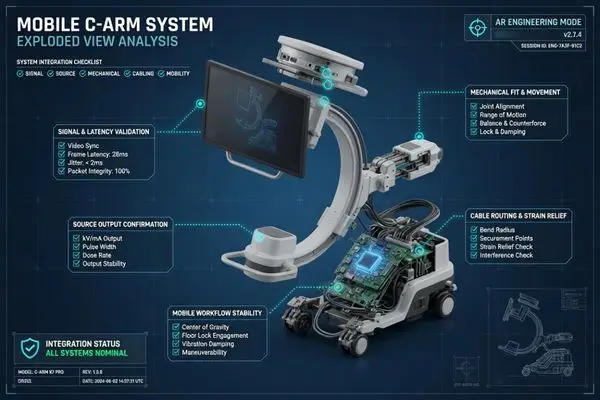
Before sample approval, the equipment manufacturer should review the display role, processor output, signal timing, end-to-end latency, mechanical fit, cable routing, power recovery, mobile workflow, and configuration control. Equipment manufacturers preparing an RFQ or sample review can use Reshin’s display integration support for C-arm and mobile imaging systems to align these requirements before model selection.
This checklist primarily addresses mobile and cart-based C-arm platforms. Fixed interventional-room displays may require additional review of room-level signal routing, multi-source layouts, viewing distance, and shared-display roles. A C-arm display should be evaluated with the real or representative processor, planned cable path, mounting structure, and mobile workflow. The objective is to determine whether the approved sample condition can be repeated during pilot production, volume production, replacement, and long-term supply.
Define the Display Role Before Reviewing Specifications
Display selection should begin with the role the display performs inside the C-arm system. A primary live fluoroscopy display, operator control display, touch-enabled equipment interface, cart-mounted display, secondary review display, and shared room display do not create the same engineering priorities.
The display role should be defined before specifications are compared. A live fluoroscopy display, control display, cart-mounted endpoint, secondary review display, and shared room display each require different review priorities for signal behavior, mounting, touch control, viewing distance, and workflow fit.
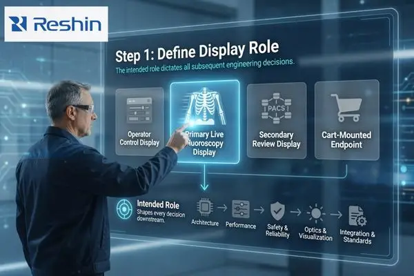
For a primary live fluoroscopy display, the main concerns are continuous image presentation, motion behavior, grayscale visibility, and acceptable end-to-end latency under the intended signal chain. An operator control display places more emphasis on software resolution, UI scaling, control readability, and touch compatibility. A cart-mounted or articulated-arm-mounted display also requires review of weight, center of gravity, mounting range, cable movement, and position-holding stability.
The equipment type should also be identified early. A compact mobile C-arm, full-size mobile C-arm, and fixed interventional C-arm platform may have different display positions, movement envelopes, viewing distances, weight limits, and cable-routing conditions.
| Display Role | Main Task | Priority Requirements | Key Question Before Sampling |
|---|---|---|---|
| Primary live fluoroscopy display | Continuous moving-image presentation | Motion, latency, grayscale visibility | Is this the main procedural display? |
| Operator control display | System UI and image control | Native resolution, UI scaling, touch | What software resolution is fixed? |
| Cart- or arm-mounted display | Imaging or equipment control | Weight, mounting, cable movement | How is the display moved and locked? |
| Secondary review display | Stored or reference images | Layout, viewing angle, consistency | Is formal diagnostic review required? |
| Shared room display | Wider team viewing | Size, viewing distance, source layout | Is it part of the equipment or room? |
The display role should be defined before deciding:
- FHD or 4K resolution
- Touch or non-touch configuration
- Grayscale presentation requirements
- Input interface direction
- Mounting method
- Display size
- Whether the display belongs to the C-arm equipment or the wider room system
This prevents a control display from being evaluated like a primary imaging display, or a shared room display from being specified like a mobile cart-mounted endpoint.
Confirm Source Output, Resolution and Signal Timing
C-arm display compatibility must be evaluated from the actual image processor, graphics platform, or workstation output. Supporting the same connector type does not automatically guarantee compatibility.
Source output validation should confirm processor model, interface, resolution, refresh rate, timing, EDID behavior, startup sequence, cable length, intermediate devices, and touch-control behavior where applicable. A display should not be approved from a general computer test alone.
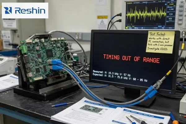
The equipment manufacturer should confirm the processor or workstation model, output interface, native output resolution, refresh rate and signal timing, color or grayscale output, EDID behavior, startup and wake-up sequence, planned cable type and length, converters, splitters, routers, reconnection behavior after power cycling, and touch-control interface where applicable.
Touch requirements should identify whether the system uses USB HID, serial control, a proprietary protocol, or a specific driver and operating-system environment. Touch calibration, wake-up behavior, and reconnection should be tested together with the display signal. Processor output, EDID, timing, touch control, and interface modules may require signal and I/O platform engineering review before a display direction is approved.
Possible integration problems include:
- Incorrect resolution recognition
- Image scaling, cropping, or stretching
- Incorrect equipment UI layout
- No signal after startup
- Black screen after reconnection
- Unstable EDID recognition
- Touch-control mismatch
- Timing changes introduced by converters
- Signal loss with production-length cables
| Item to Confirm | Information Required | Main Risk | Sample Test |
|---|---|---|---|
| Source device | Processor or workstation model | Unknown output behavior | Test with the actual or representative source |
| Output interface | HDMI, DP, DVI, SDI, or other | Converter dependence | Test the planned production path |
| Native resolution | Actual output resolution | Scaling or incorrect UI layout | Confirm the approved screen layout |
| Frame rate and timing | Planned output timing | No signal or unstable motion | Test every planned timing mode |
| EDID and startup | Recognition and power sequence | Startup failure | Repeat cold-start and wake-up tests |
| Touch interface | USB, serial, driver, or protocol | Control mismatch | Test calibration and reconnection |
| Cable length | Actual installation length | Signal instability | Test production-length cables |
| Intermediate devices | Converter, router, or splitter | Added delay or handshake failure | Test the complete signal chain |
The sample should be evaluated with the real processor or a representative source, the planned cable length, and all intermediate devices expected in the final equipment. If the production system uses a converter, splitter, long internal cable, or fixed power-up sequence, the display should not be approved from a short direct connection to a general-purpose computer.
Evaluate End-to-End Latency and Motion Behavior
Fluoroscopy presents continuous X-ray images on a monitor, so a display used in a C-arm workflow should be evaluated with representative moving output rather than a static image alone.1
C-arm latency should be assessed across the complete imaging chain, not from panel response time alone. The equipment manufacturer should test representative motion, source switching, reconnection, startup behavior, and planned signal-path configurations before approving the display sample.
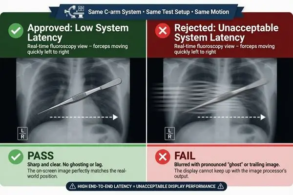
C-arm latency should be assessed across the complete imaging chain:
Image source or detector → Image processor → Video output → Converter or router → Cable → Display processing → Panel
Panel response time is only one component of end-to-end system latency. The same display may produce different results when used with different processors, cables, converters, routing devices, firmware, or image-processing settings. A universal latency limit should therefore not be applied without considering the equipment manufacturer’s intended workflow and complete-system verification plan.
A representative test should include:
- Continuous output from the intended processor or a representative moving-image sequence
- Movement of instruments or test objects
- Image panning and zooming
- Switching between live and stored images
- C-arm or cart repositioning
- Input disconnection and reconnection
- Cold startup and wake-up
- Extended operating sessions
- Different planned signal-path configurations
The test result should not be recorded only as “fast” or “slow.” A structured engineering decision may use categories such as:
- Pass
- Conditional pass
- Adjustment required
- Retest required
- Not approved
A conditional pass may be appropriate when the display works only with a defined processor timing, cable length, or routing configuration. Retesting may be required if the converter, input board, firmware, cable, or processor output changes after the first sample review.
Validate Mechanical, Cable, Power and Mobile Workflow Integration
Mechanical and mobile validation should confirm that the display remains stable and usable while the C-arm, cart, articulated arm, cables, and power components are moved and repositioned.
A stationary bench test does not represent a mobile C-arm workflow. The sample should be tested for mechanical stability, cable movement, power recovery, connector retention, touch operation, and configuration recovery during representative movement and repositioning.
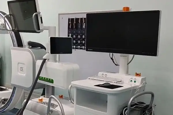
A stationary bench test does not reproduce the movement envelope of a mobile imaging system. Mechanical review should include overall dimensions, installed weight, center of gravity, VESA pattern and mounting plate, arm or cart load capacity, tilt and rotation range, position-holding stability, required repositioning force, collision clearance, connector access, ventilation and heat path, service access, and touch-operation stability.
Protective glass, touch layers, customized housings, and additional interface modules may change the installed weight and center of gravity. These changes should be included in the final mechanical configuration rather than assessed only from the standard display specification.
Cable and power review should include:
- Actual cable route
- Cable slack at pivot points
- Bend radius
- Pinch points
- Strain relief
- Connector retention
- Interference with handles or wheels
- Power adapter placement
- DC connector retention
- Signal recovery after movement
- Power recovery after interruption
A representative mobile workflow can follow this sequence:
- Move the C-arm or cart into position.
- Lock the equipment.
- Adjust the display angle and height.
- Start or reconnect the processor.
- Confirm the approved input and resolution.
- Display representative moving images.
- Reposition the C-arm, cart, or display arm.
- Confirm signal and power stability.
- Test the touchscreen or equipment UI.
- Restart the system and confirm configuration recovery.
| Workflow Stage | Main Check | Potential Risk | Evidence |
|---|---|---|---|
| Move into position | Cable and power stability | Disconnection or cable pulling | Movement record |
| Lock and adjust | Mounting and position stability | Drift, vibration, or collision | Mechanical record |
| Start source | Signal recognition | Wrong input or resolution | Startup record |
| View moving images | Motion and latency | Lag or unstable presentation | Image test |
| Reposition system | Signal continuity | Black screen or interruption | Repeat test |
| Use touch or UI | Structural and software response | Display movement or control failure | Touch/UI test |
| Restart | Approved configuration recovery | Incorrect startup state | Power-cycle record |
Static fit, dynamic repositioning, cable stress, and startup recovery should be recorded separately. A sample that passes only a stationary VESA fit check should not be treated as approved for mobile use.
Create a Sample Acceptance Record and Freeze the Approved Configuration
A successful sample test should be converted into a documented and repeatable approved configuration. One working sample does not prove that pilot production, volume production, replacement units, or future batches will behave in the same way.
Sample approval should become a controlled configuration record. The approved baseline should include hardware, firmware, input board, source device, timing, cable route, mounting, power, default settings, touch behavior, known limitations, reviewers, and approval status.
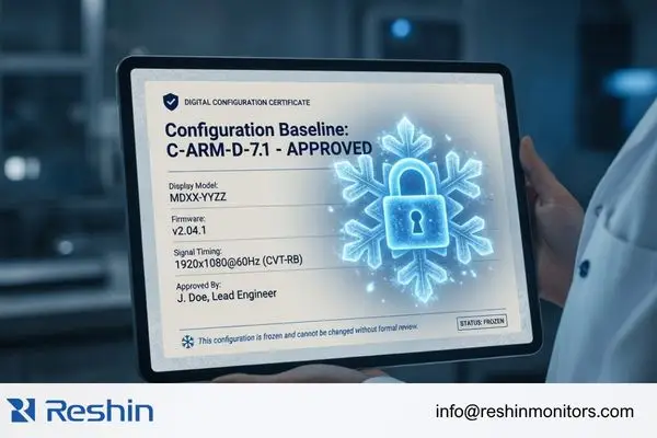
The approved baseline should record:
- Display model
- Hardware configuration
- Firmware version
- Input-board configuration
- Processor or source device
- Resolution and timing
- Cable type and length
- Converter, splitter, or routing device
- Mounting structure
- VESA pattern and accessories
- Power configuration
- Default image mode
- Touch protocol and settings
- Test conditions
- Known limitations
- Approved application role
- Responsible reviewers
- Final approval status
Responsibilities should also be defined. The system or electrical engineer may confirm signal compatibility. The imaging or application engineer may review motion and image behavior. The mechanical engineer may review mounting and movement stability. The quality team may control the approved document set. The project manager may confirm the approved project scope.
Maintaining the approved hardware, firmware, input-board, accessory, and inspection baseline depends on controlled medical display manufacturing and quality control throughout pilot and volume production. The approved condition must also remain visible during replacement and future supply. This is where long-term supply and model consistency becomes part of the engineering record.
A frozen configuration does not mean that nothing can change. It means that changes to firmware, cables, input boards, mounting parts, power configuration, accessories, or documentation should be identified, reviewed, and connected to the original approval record. The team can then decide whether the change requires document review, limited confirmation testing, or full revalidation.
Complete C-Arm Display Integration Checklist Before Sample Approval
This checklist combines the main review areas into one sample-stage framework. It can support engineering review, RFQ preparation, sample testing, cross-functional approval, and configuration control.
The checklist should help the equipment manufacturer collect required information, identify project risk, define validation methods, record evidence, and control the approved configuration before pilot or volume production. It is not a regulatory checklist or a substitute for complete-system verification.
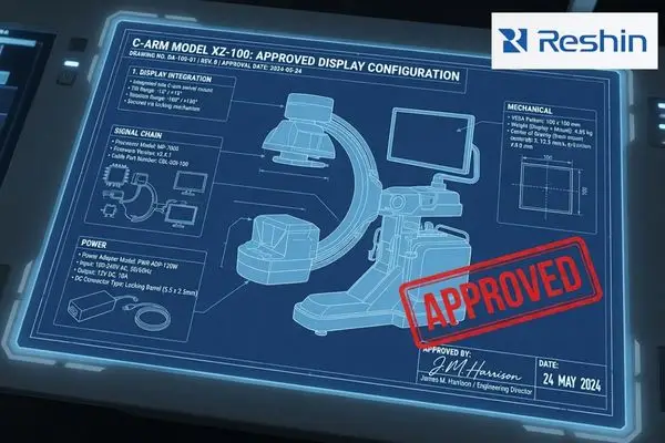
It is not a regulatory checklist and does not replace verification of the complete C-arm system by the equipment manufacturer. IEC 60601-2-43 addresses fixed and mobile X-ray equipment declared suitable for radioscopically guided interventional procedures, while IEC 60601-2-54 addresses X-ray equipment for radiography and radioscopy.23 The applicable requirements depend on the intended use and final equipment classification. Display-level review alone does not establish compliance of the complete system.
| Checklist Area | Information Required | Main Risk | Validation Method | Evidence Output |
|---|---|---|---|---|
| System type | Compact mobile, full-size mobile, or fixed/interventional | Wrong integration assumptions | Equipment architecture review | Scope definition |
| Display role | Position, user, and workflow | Wrong display direction | Workflow review | Role definition |
| Source output | Interface, resolution, and timing | No image or scaling | Full-chain source test | Signal record |
| Startup and EDID | Power and recognition behavior | Startup failure | Repeated power cycles | Startup log |
| Touch and UI | Protocol, driver, and software layout | Control mismatch | Equipment UI test | Touch record |
| Latency and motion | Complete imaging chain | Delayed or unstable motion | Representative moving-image test | Acceptance summary |
| Mechanical fit | Dimensions, weight, VESA, and center of gravity | Instability or collision | Mechanical test | Mounting record |
| Movement envelope | Cart path, arm range, and pivot points | Cable stress or obstruction | Repeated movement test | Movement record |
| Cable and power | Route, retention, and power configuration | Signal or power interruption | Movement and power-cycle test | Routing and power record |
| Configuration | Model, firmware, accessories, and settings | Sample-to-production drift | Document review | Frozen baseline |
| Lifecycle | Supply and change requirements | Future configuration mismatch | Supplier review | Continuity plan |
After the checklist is complete, the team can discuss initial product directions. Product selection should remain the result of the engineering review rather than the starting point. Teams comparing potential C-arm and radiology monitor options should first confirm the application role, source output, mounting condition, and intended use.
A compact FHD touchscreen direction may suit some smaller C-arm platforms, while a larger 4K touchscreen may be considered where the processor output, equipment UI, and mounting structure support it. For example, the MD80CTOR 4K touchscreen medical monitor can be evaluated for suitable C-arm, fluoroscopy, or interventional imaging projects. Its suitability still depends on project-specific signal, touch, mechanical, power, and workflow validation.
Large-format Cath Lab displays should be evaluated separately when the requirement involves a fixed interventional room, shared viewing, or a multi-source room layout rather than a mobile C-arm equipment endpoint.
Frequently Asked Questions About C-Arm Display Integration
C-arm display integration questions usually come from the gap between sample appearance and system-level repeatability. I answer these questions from the standpoint of processor output, display role, signal chain, mobile workflow, and approved configuration control.
The most important C-arm display integration questions are not only about resolution or interface type. The project team should confirm whether the display direction matches the source output, equipment role, touch behavior, motion testing plan, and sample acceptance criteria.
Is 4K required for every C-arm display project?
No. The requirement depends on processor output, display role, equipment UI, viewing distance, image layout, and project acceptance criteria.
A 4K display does not automatically add original image detail when the source outputs only FHD. It may also introduce additional scaling, graphics-output, and compatibility checks.
Is 12G-SDI always the best interface for a C-arm monitor?
No. Interface selection should be based on the processor output, cable length, equipment structure, converters, movement conditions, and complete signal path.
HDMI, DisplayPort, DVI, SDI, or another interface may be appropriate in different projects. The important question is whether the approved chain remains stable and repeatable in the final equipment configuration.
How should latency be tested in a C-arm display system?
Latency should be tested through the complete imaging chain using the real or representative processor, planned cables, converters, routers, and display settings.
Testing should include moving images, switching, reconnection, startup, repositioning, and extended operation. Panel response time alone is not sufficient to represent complete-system latency.
What information is required before requesting a C-arm display sample?
The equipment manufacturer should provide:
- C-arm system type
- Display position and role
- Processor or workstation model
- Output interface
- Resolution and refresh rate
- Touch interface and operating system
- Installation drawing
- VESA pattern
- Display weight limit
- Movement range
- Cable and power requirements
- Target market
- Sample schedule
- Estimated quantity
- Current project stage
This information supports the initial display and sample direction, but final compatibility still depends on project-specific validation.
Approve the Display as Part of the Complete Mobile Imaging System
A C-arm display should be approved as part of the complete equipment configuration, not from a specification sheet or one successful bench connection.
A valid C-arm display evaluation should connect display role, processor output, signal compatibility, end-to-end latency, motion behavior, mechanical installation, cable and power stability, mobile workflow, acceptance documentation, and approved configuration repeatability.
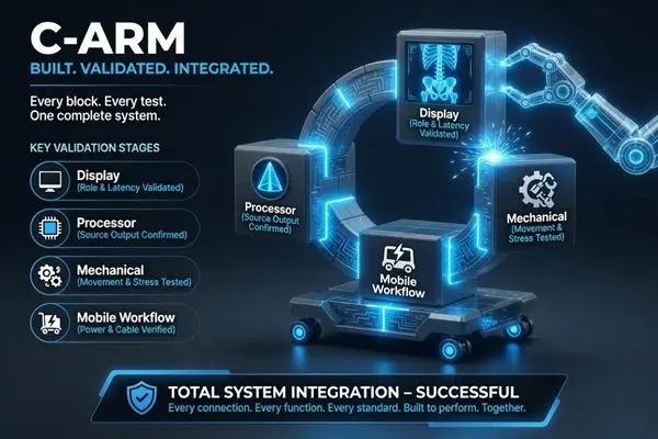
The approved result should connect the source path, mechanical installation, mobile workflow, and configuration record so that the same condition can be repeated during pilot and volume production.
A practical project sequence is:
Define the display role → Map the source output → Test the complete signal chain → Validate mounting and movement → Record sample acceptance → Freeze the approved configuration
Reshin can review an initial display direction based on the C-arm system type, display role, processor output, resolution and frame rate, touch interface, mounting structure, target market, and current project stage. For early project evaluation, review Reshin’s C-arm display integration support for equipment manufacturers.
Request C-Arm Integration Review
Share your C-arm system type, display position, processor output, resolution and frame rate, touch requirements, mounting structure, movement range, target market, and current project stage for an initial display integration review.
- Fluoroscopy — U.S. Food and Drug Administration. The FDA describes fluoroscopy as medical imaging that shows a continuous X-ray image on a monitor. This supports evaluating representative moving output instead of relying only on static images. ↩
- IEC 60601-2-43:2022 — Medical electrical equipment for radioscopically guided interventional procedures. The standard applies to the basic safety and essential performance of fixed and mobile X-ray equipment declared suitable for radioscopically guided interventional procedures. Applicability depends on the complete equipment and intended use. ↩
- IEC 60601-2-54:2022 — X-ray equipment for radiography and radioscopy. This standard addresses X-ray equipment and systems intended for projection radiography and radioscopy. It is included only as system-level standards context and does not establish compliance of a standalone display or customer equipment. ↩