Changing a surgical display from frame bonding to full optical bonding can appear straightforward. For an OEM, however, it changes an approved configuration and requires controlled review before release.
An optical bonding process change should be treated as a controlled configuration change, not simply as a cosmetic upgrade. OEMs should define the approved baseline, identify what has changed, revalidate the affected optical, mechanical, surface and reliability characteristics, review updated supplier evidence, and control the transition between old and new production batches.

A surgical display may still power on, accept the same video signal and show a normal image after its front structure changes. Those basic checks are necessary, but they do not establish that the changed version remains equivalent to the configuration previously approved by the OEM.1
Moving from frame bonding to full optical bonding introduces a different optical stack and manufacturing process. Depending on the actual change, it may affect reflection, luminance, color behavior, visible area, surface treatment, mechanical fit, long-term adhesion and production inspection. The scope should therefore be reviewed before the changed configuration enters pilot or repeat production.
For endoscopy equipment manufacturers and surgical system integrators, this is part of evaluating a surgical monitor manufacturer for controlled OEM projects, not merely comparing display specifications.
What Exactly Changes When a Surgical Display Moves from Frame Bonding to Full Optical Bonding?
The first task is to define the physical change accurately. Protective glass, frame bonding, surface treatment and full optical bonding describe different parts of a display assembly and should not be used interchangeably.
Frame-Bonded Protective Glass Structure
In a frame-bonded structure, the protective glass is normally fixed around its perimeter. An air gap generally remains between the glass and the LCD panel, although the exact assembly depends on the product design.
The protective glass, bonding frame and LCD remain relatively separate parts of the front structure. The resulting performance depends on the glass, coatings, gap, frame material, assembly tolerance and panel surface.
Full Optical Bonding Structure
In a fully bonded structure, an optically clear bonding material fills the space between the cover glass and the LCD surface. The glass, bonding layer and panel therefore form a new optical and mechanical stack.
A properly designed bonded stack may reduce internal air interfaces2, but the actual result still depends on the glass, surface coating, bonding material, refractive characteristics, bonding thickness, curing process, cleanliness and panel condition. Full bonding should not automatically be described as improving every optical or reliability metric.
Protective Glass and Surface Treatment Are Separate Variables
A surgical display can have protective glass without being fully bonded. It can also use anti-reflective, anti-glare or other surface treatments regardless of how the glass is attached.
OEMs should therefore identify exactly which elements are changing:
- Bonding method
- Cover-glass material
- Glass thickness
- Surface coating
- Bonding material
- Bonding-layer thickness
- LCD panel
- Mechanical structure
- Manufacturing process
- Inspection criteria
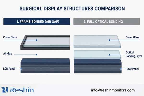
The change boundary determines the revalidation boundary. If the bonding method changes while the LCD panel, glass, coating, housing, firmware and video electronics remain unchanged, the review can focus on the directly affected areas and essential regression checks. If several parts of the optical stack change together, a wider validation scope is justified.
Why Normal Image Output Is Not Enough for OEM Approval
A normal image proves that the changed display can perform a basic function under the tested condition. It does not prove that the new configuration matches the approved version across optical, mechanical, environmental and production requirements.
An OEM may receive a changed sample that powers on, recognizes the camera processor and displays a stable image. That result does not answer whether:
- Reflection has changed under operating-room lighting
- Measured luminance remains consistent with the approved baseline
- White point or color behavior has shifted
- The visible image area has changed
- The glass creates new mechanical stress on the LCD
- Surface coatings remain compatible with approved cleaning instructions
- Bubbles, particles or edge defects are adequately controlled
- The bonded structure remains stable after environmental or transportation exposure
- Production units can repeat the sample result
- Old and new configurations can be distinguished
These possibilities do not mean that a bonding change will necessarily create a problem. They mean that the earlier approval cannot automatically cover characteristics that may have been altered by the new material stack and process.
The objective is not to repeat every historical test without justification. The objective is to identify the affected characteristics, retain reasonable regression coverage and document why the selected verification scope is sufficient.
Start with the Approved Baseline and a Defined Change Boundary
Before deciding what to test, the OEM and display supplier should establish what was previously approved. Without a baseline, the changed sample can only be judged in isolation.
An approved baseline may include:
- Display model and controlled configuration
- LCD panel direction
- Protective-glass specification
- Surface treatment
- Bonding method
- Mechanical drawing revision
- Visible and active image area
- Approved image settings
- Firmware and OSD version
- Interface configuration
- BOM revision
- Inspection specification
- Approved sample status
- Labeling and product identification
- Relevant system conditions
The next step is to separate changed and unchanged items. A change description that only says “frame bonding changed to full bonding” is not enough for approval. It should clarify whether the glass, coating, panel, adhesive, mechanical parts or supplier have also changed.
The review should answer:
- What was the approved configuration?
- What exactly is being replaced or modified?
- Which characteristics may be directly affected?
- Which functions remain technically unchanged?
- Which documents require revision?
- How will the changed version be identified?
- When will the new configuration enter production?
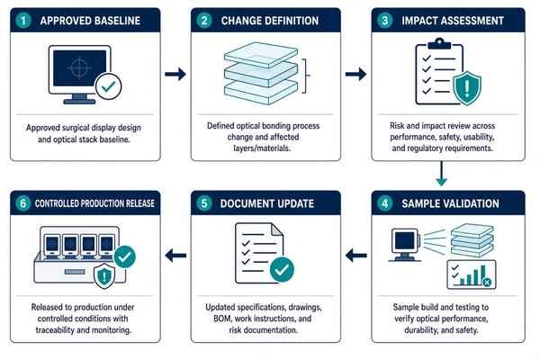
A controlled medical display configuration review should preserve unaffected parts of the approved platform while identifying the areas that genuinely require additional evidence. This avoids both under-testing a meaningful change and unnecessarily reopening the complete product specification.
What Should OEMs Revalidate After an Optical Bonding Process Change?
The correct revalidation scope depends on the proposed configuration, intended application, previous approval evidence and system-level risk assessment. The following areas should be reviewed as potential change impacts rather than treated as a universal test prescription.
Optical Performance
Changing the material between the cover glass and LCD modifies the optical path. Even when the LCD panel remains the same, the completed assembly should be compared with the approved baseline under controlled conditions.
Relevant review points can include:
- Measured luminance at an agreed image setting
- Black level and resulting contrast
- Reflection and glare under defined ambient lighting
- Haze and luminous transmission where applicable
- White point
- Color reproduction
- Grayscale behavior
- Luminance and color uniformity
- Viewing-angle behavior
- Visible image area
- Edge and corner appearance
- Bubbles, particles, Mura or local optical defects
The measurement conditions matter. Luminance comparisons should use the same signal source, image pattern, OSD setting, warm-up condition and measurement method. A value measured under a different configuration cannot provide a reliable before-and-after comparison.
The article should not assume that full optical bonding always increases measured luminance. Bonding may change internal reflection and environmental contrast3, but the final result depends on the complete optical stack. The OEM should approve measured performance against its agreed project criteria, not a general marketing statement.
Where a surgical display project includes specific color-space or image-preset requirements, those items should be checked against the approved project configuration. Diagnostic-display DICOM requirements should not be inserted into a surgical application unless they are genuinely part of that project.
Mechanical and Integration Fit
Full optical bonding can change more than the front appearance. The completed bonded module may have a different thickness, weight, stiffness or tolerance condition.
Mechanical review can include:
- Overall front-stack thickness
- Product weight and center-of-gravity impact
- Glass and housing fit
- Bezel clearance
- Active and visible area alignment
- Edge gaps
- Mounting compatibility
- Stress applied to the LCD panel
- Front-key, sensor or touch alignment where applicable
- Compatibility with the equipment tower, cart, arm or enclosure
- Packaging and transportation support
A sample can fit into an equipment structure while still creating excessive local pressure or inadequate clearance. OEM evaluation should therefore consider assembly condition and repeatability, not only the nominal external dimensions.
If the change alters product weight or front-section stiffness, cart stability, mounting behavior or equipment integration may require additional OEM review. These are system-level decisions and should not be concluded from display-supplier measurements alone.
Surface, Cleaning and Handling
The bonding method does not by itself define the external surface. OEMs should confirm whether the cover glass, coating or edge construction changes with the bonded version.
Review points may include:
- Surface coating identification
- Appearance after repeated wiping
- Compatibility with cleaning agents permitted by the product instructions
- Scratch and fingerprint behavior
- Glass-edge condition
- Residue or discoloration
- Protection during assembly and transportation
- Handling instructions for production and service
A smoother front surface may simplify physical wiping, but that does not prove compatibility with every cleaning or disinfection chemical. Claims should be limited to the actual glass, coating, cleaning instructions and available test evidence.
If the external surface remains unchanged, the supplier should document that fact. If the glass or coating also changes, cleaning and surface evidence should be included in the change review.
Environmental and Reliability Behavior
Optical bonding introduces materials and interfaces whose stability depends on material selection and process control. Reliability checks should be selected according to the changed materials, intended environment and previously approved validation plan.
Potential observations include:
- Bubble formation
- Edge lifting or delamination
- Yellowing or haze development
- Bonding-layer movement
- Local optical non-uniformity
- Glass or panel stress
- Performance after temperature or humidity exposure
- Appearance after transportation or vibration
- Stability after extended display operation
Not every project requires the same environmental test sequence. A display supplier should explain why the selected tests are relevant and how their conditions relate to the proposed configuration. The OEM should then determine whether the evidence is sufficient for its complete equipment program.
A short visual inspection immediately after bonding cannot establish long-term process stability. At the same time, a bonding change should not automatically trigger every reliability test previously conducted on the complete device. The scope should be proportional to the actual change and documented risk.
Functional and System-Level Regression
When only the optical stack changes, the video electronics, interfaces and firmware may remain unaffected. Even so, basic regression testing helps confirm that the changed sample represents a complete and usable production configuration.
Regression checks can include:
- Power-on and shutdown
- Stable image display
- Required input signals
- Image presets
- OSD functions
- Front controls
- Touch or sensor operation where applicable
- Power interruption and recovery
- Installation in the intended equipment
- Viewing under representative lighting and viewing positions
A change to optical bonding does not automatically require full revalidation of every HDMI, DisplayPort or SDI format. However, if the LCD panel, mainboard, firmware or front-control design changes at the same time, the signal and functional scope should be expanded.
OEMs evaluating surgical monitor platforms for endoscopy integration should keep display-level regression testing separate from connected-system approval. The final equipment manufacturer remains responsible for determining whether the changed display is acceptable in the complete surgical or endoscopy system.

Optical Bonding Change Revalidation Matrix
The revalidation matrix should connect each possible impact to a verification activity, acceptance basis, evidence record and responsible party. It should not use one universal numerical threshold for every surgical display project.
| Review Area | Potential Change Impact | Suggested Verification | Acceptance Basis | Expected Evidence | Primary Responsibility |
|---|---|---|---|---|---|
| Optical stack | Reflection, haze or transmission change | Controlled comparison with approved sample | Agreed project criteria | Optical comparison record | Supplier and OEM |
| Luminance | Output variation after bonding | Measurement under matched settings | Approved baseline or specification | Measurement report | Display supplier |
| Color and grayscale | White-point, color or tonal change | Controlled test images and measurements | Project image requirements | Test data | Supplier and OEM |
| Uniformity | Local variation or edge effects | Multi-point visual and measured review | Approved inspection criteria | Inspection record | Display supplier |
| Visible area | Image or bezel alignment change | Dimensional and image-area check | Approved drawing and sample | Dimensional record | Display supplier |
| Mechanical fit | Thickness, weight or stress change | Assembly and equipment-fit review | Approved mechanical requirements | Fit-check record | Supplier and OEM |
| Surface | Coating or cleaning impact | Material-specific review | Approved material and cleaning requirements | Material or test evidence | Supplier and OEM |
| Reliability | Bubble, delamination or aging risk | Defined environmental or operating checks | Project validation plan | Reliability evidence | Display supplier |
| System integration | Viewing or installation impact | Connected-equipment evaluation | OEM system criteria | System validation record | OEM or system manufacturer |
| Batch control | Mixing of old and new configurations | Lot, serial and cut-in review | Approved transition plan | Traceability record | Display supplier |
The matrix should be adapted rather than copied without review. A project that changes the bonding material, cover glass and LCD panel together will require broader evidence than a project changing only the bonding method with all other controlled items unchanged.
If the project is already in production, the matrix should also identify whether existing finished goods, spare parts and field-service stock are affected. Approval should cover not only the changed sample but also the intended production and transition conditions.
If your OEM project is evaluating a change from frame bonding to full optical bonding, define the current display configuration, changed materials, intended surgical system, approval stage and required evidence before requesting a new sample. This makes the sample evaluation more useful and reduces late-stage disagreement about what was actually approved.
What Evidence Should the Surgical Display Supplier Provide?
A supplier change package should make the proposed configuration understandable to engineering, quality, procurement and project teams. The purpose is not to disclose every controlled manufacturing detail, but to provide enough evidence for an informed approval decision.
Depending on project scope, the package may include:
- ECR, ECN or PCN reference
- Reason for the change
- Affected display models or configurations
- Before-and-after change description
- Identification of affected materials
- Updated BOM or drawing revision
- Optical-stack or material description
- Change-impact assessment
- Sample validation plan
- Display-level test results
- Updated inspection criteria
- Sample and production revision identification
- Inventory treatment
- Planned effective date
- Customer-review and approval status
The supplier should also identify what did not change. If the panel, firmware, mainboard, interface set and external glass treatment remain the same, documenting those boundaries helps prevent unnecessary assumptions.
Evidence availability should be stated carefully. Public website information, project-review documents and controlled engineering records do not have the same disclosure level. Customer identities, internal material numbers, detailed process parameters and controlled drawings may need to remain confidential.
Reshin’s medical display engineering change project experience illustrates how project context, model-level evidence and confidential engineering records can be separated. The existence of an ECN is useful evidence of process control, but the ECN alone does not prove that every required optical, mechanical or system-level verification has been completed.
How Should Samples, Pilot Units and Batch Cutover Be Controlled?
A technically acceptable changed sample can still fail as a production change if its identity, manufacturing configuration or release timing is unclear. OEM approval should therefore extend from the sample to the controlled production transition.
Changed Sample Identification
The supplier should identify:
- That the sample uses the proposed full-bonded configuration
- The relevant glass and panel direction
- The bonding-process revision
- Firmware and electronic configuration
- Sample serial or revision identification
- Whether the sample represents production-intent materials
- Any temporary deviation from the planned production version
An unmarked sample creates uncertainty later. If the approved sample cannot be connected to the BOM, drawing and production revision, the OEM may not know whether subsequent deliveries use the same configuration.
Pilot or First Controlled Batch
The first controlled batch should confirm that the process can repeat the approved sample result. Review points may include:
- Bonding cleanliness
- Bubble and particle control
- Edge appearance
- Optical consistency
- Mechanical fit
- Inspection execution
- Work instructions
- Traceability
- Handling and packaging
- Nonconformance control
This stage is different from approving a single engineering sample. The question is no longer only whether one unit performs correctly, but whether the approved configuration can be reproduced and inspected consistently.
Cut-In and Inventory Control
The transition plan should define:
- The effective date
- The last old-configuration unit
- The first new-configuration unit
- Treatment of existing raw materials
- Treatment of finished goods
- Spare and service-stock implications
- Whether old and new versions may both be supplied
- How each version will be identified
- Whether customer approval is required before release
- What happens if the changed version is not approved
An Anonymized Change-Control Example
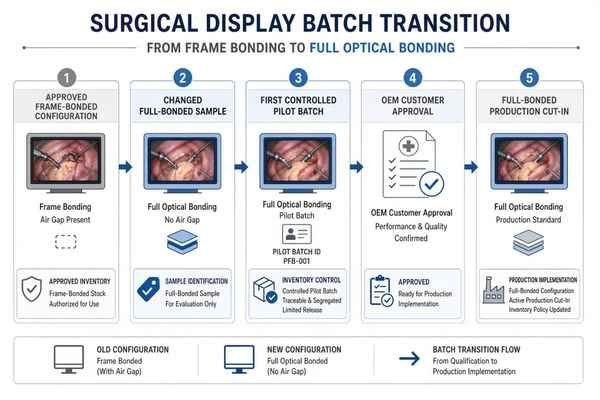
In one established surgical display configuration, a project request proposed changing the front structure from frame bonding to full optical bonding.
The change was processed through controlled ECR and ECN records. The review addressed the affected assembly materials, BOM and inspection-document updates, functional verification, existing inventory, production implementation, cross-functional approval and customer acknowledgement. The released record also defined the transition into the changed configuration.
This case demonstrates several important change-control elements, but it should not be presented as proof that all optical, environmental and long-term reliability characteristics are automatically equivalent. Those conclusions require project-specific evidence. The public article should therefore use the case to explain the control process rather than disclose the model, internal material numbers, signatures or confidential test details.
Who Is Responsible for What During Approval?
Responsibility should be assigned according to the evidence each party controls.
The bonding-material or bonding-process supplier may provide material information, process evidence and upstream change notification. It does not normally approve the completed surgical system.
The surgical display supplier should define the display-level change, maintain component and revision traceability, build representative samples, perform agreed display-level checks, update controlled documents and manage the production cut-in.
The OEM or medical equipment manufacturer should determine the effect on intended use, complete-system performance, project risk, customer documentation and market-specific regulatory files. It also defines the final system-level acceptance criteria.
A separate system integrator may need to confirm installation, connected-equipment behavior and deployment conditions when it owns those parts of the project.
A design, component or manufacturing-process change should not be described as automatically requiring a new regulatory submission. It should also not be described as automatically having no regulatory impact. That decision belongs to the legal manufacturer and depends on the device, intended use, target market, risk assessment and applicable regulatory process.
Supplier validation can support the OEM decision. It cannot replace the OEM’s responsibility for the finished medical equipment.
Common Approval Mistakes OEM Buyers Should Avoid
Treating Full Optical Bonding as a Cosmetic Upgrade
The external appearance may be the most visible difference, but the change also introduces a new material stack and manufacturing process. The impact review should reflect those changes.
Approving the Change Because the Display Shows a Normal Image
A normal image does not address reflection, luminance, mechanical stress, surface compatibility, bonding stability or batch control.
Comparing the Changed Sample Without an Approved Baseline
Without controlled before-and-after conditions, differences may be overlooked or attributed to unrelated settings.
Approving a Sample Without Approving the Production Configuration
A sample may use temporary materials or non-production processes. The approved sample must be connected to the intended BOM, drawings, inspection criteria and production revision.
Updating the BOM but Not the Inspection Criteria
New bonding materials and processes may introduce different defect types. Inspection standards should reflect the changed configuration.
Failing to Define the Batch Transition
If old and new versions cannot be distinguished, complaints, service actions and future change reviews become more difficult.
Assuming Supplier Testing Equals Final System Approval
The display supplier can verify display-level performance. The OEM must still determine the impact on the complete surgical or endoscopy equipment.
OEM Checklist Before Approving an Optical Bonding Process Change
Use the following checklist as a project starting point rather than a universal regulatory requirement:
- The reason for the optical bonding process change is documented.
- The affected display model and configuration are identified.
- The previously approved baseline is available.
- Changed and unchanged items are separated.
- Cover-glass material and thickness are defined.
- Surface treatment is confirmed.
- Bonding material and process direction are identified.
- LCD panel status is confirmed.
- Optical performance is compared under controlled conditions.
- Mechanical and equipment fit are verified.
- Surface and cleaning impact are reviewed.
- Reliability scope is justified by the actual change.
- Basic functional regression is completed.
- System-level validation is completed where required.
- BOM, drawings, specifications and inspection documents are updated.
- Changed samples are traceable.
- Pilot or initial-batch controls are defined.
- Old and new inventory treatment is documented.
- Production cut-in and version identification are controlled.
- OEM approval and effective date are recorded.
A completed checklist should point to evidence rather than rely on yes-or-no statements alone. Each checked item should be supported by a document, measurement, sample record, inspection result or responsible approval.
FAQ About Optical Bonding Process Change Approval
Does changing from frame bonding to full optical bonding require complete system revalidation?
Not automatically. The scope should be based on the actual materials, process, mechanical structure and product functions affected by the change. Display-level optical and mechanical checks are normally relevant, while broader system testing depends on the OEM’s risk assessment, intended application and previously approved configuration.
Is full optical bonding always better for a surgical display?
No. Full optical bonding can change internal reflection, environmental contrast, structure and surface behavior, but the result depends on the complete optical stack and manufacturing process. OEM approval should be based on measured performance and project requirements rather than the bonding method alone.
Is a functional test enough to approve the change?
A functional test is useful but normally insufficient as the only evidence. It confirms basic operation under the tested condition but does not cover possible optical, mechanical, surface, reliability, documentation and production-transition impacts.
What documents should a surgical display supplier provide?
The expected package may include the change notice, affected configuration, before-and-after description, impact assessment, revised documents, validation evidence, inspection updates, sample identification, inventory treatment, cut-in date and customer-approval status. The exact package should match the project and confidentiality boundaries.
Can frame-bonded and fully bonded versions use the same model name?
They may remain under the same commercial model in some projects, but the internal configurations should still be controlled and traceable. The supplier and OEM should define revision identification, batch separation, approval status and whether both versions can be delivered during the transition.
Conclusion
An optical bonding process change should be approved as a controlled configuration, not as a general claim that full bonding is better. OEMs should establish the approved baseline, identify the real change boundary, revalidate affected characteristics, review supplier evidence and control samples, documents, inventory and production cut-in. The final decision should confirm that the changed configuration is suitable, traceable and repeatable for the intended equipment project.
Reshin supports surgical and endoscopy equipment projects through configuration review, optical and mechanical evaluation, sample coordination, display-level verification, controlled document updates and production change management. Share your current bonding structure, proposed optical change, surgical system type, display size, surface requirements, target market and project stage. Reshin can help review the appropriate display-level validation direction, evidence requirements and next steps before the changed configuration moves toward pilot or repeat production.
✉️ info@reshinmonitors.com
🌐 https://reshinmonitors.com/
-
"Change Management for Medical Devices [Guide] – Greenlight Guru", https://www.greenlight.guru/blog/change-management-medical-devices. FDA guidance specifies that simple functional tests like powering on or displaying an image may not sufficiently demonstrate substantial equivalence for a medical device design change. Evidence role: definition; source type: government. Supports: Basic functional checks (power-on, video display) do not guarantee that a modified display remains equivalent to an OEM-approved configuration.. Scope note: Specific to U.S. FDA regulations and may not reflect other jurisdictions. ↩
-
"Air Bonding vs Optical Bonding: Which Is better for you – Rocktech Displays", https://www.rocktech.com.hk/rocktech-blog/air-bonding-vs-optical-bonding-which-is-better-for-your-display-project/. Optical bonding using index-matched adhesives fills the gap between cover glass and panel, thereby eliminating internal air interfaces and reducing Fresnel reflections. Evidence role: mechanism; source type: paper. Supports: A properly designed bonded stack may reduce internal air interfaces. Scope note: Effectiveness depends on adhesive refractive index and precise bond thickness. ↩
-
"Enhancing TFT Display Performance with Optical Bonding", https://crystal-display.com/enhancing-tft-display-performance-with-optical-bonding/. Describes how optical bonding reduces interface reflections and can enhance contrast under ambient lighting, noting outcome depends on the overall optical stack design. Evidence role: mechanism; source type: paper. Supports: Bonding may change internal reflection and environmental contrast, but the final result depends on the complete optical stack.. Scope note: Findings are based on specific display stacks and may not generalize to all materials or assembly methods. ↩